Tra
cto
rs,
Lawn
and
Garden
-
110
and
112
En
gi
ne
20
SM
-2059-(Apr
-67)
Piston
, C r a
nkshaft
and
F lyw
hee
l - T
ecumseh
35
-15
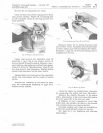
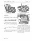
A
TT
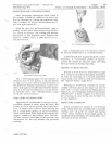
ACHING
ROD
TO
CRANKSHAFT
F
ig.
35
-
Timing
Ma
rk
s
an
C
ranks
haft
ond
Cam
sh
af
t
INST
AL
LING
CYLI
N
DER
COVER
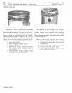
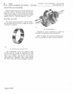
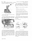
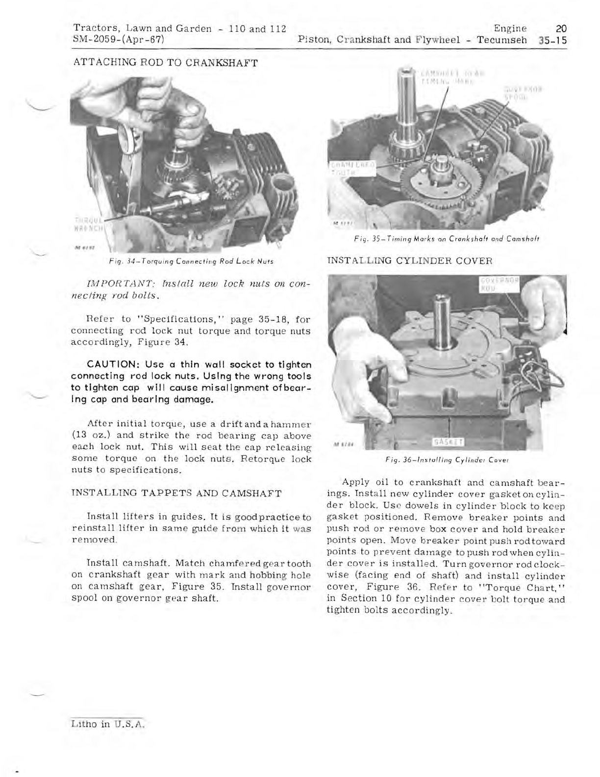
F
ig
.
34-
T
orquing
C
onn
ecti
ng
R
od
L
ock
N
uts
1M
POR
TANT:
Ins
ta
ll
n
ew
lock
nuts
on
con-
necting
rod
bolts
.
Refer
to
"Specifications,"
pag
e 35- 18, for
connecting
r od
lock
nut
torque
and
t
orq
ue
nuts
accordingly,
Figure
34.
CAUTION:
Use
a thin
wall
socket to tighten
connecting rod lock nuts. Using the wrong tool s
to tighten cap
will
cause
misalignment
of
bear-
Ing cap and
bearing
damage.
After
initi
a l t
orq
ue,
us
e a
drift
and
a
ham
m e r
(13
oz.)
and
strike
the
rod
bearing
cap
above
each
lock
nut.
This
will
seat
the
cap
re
l
eas
in
g
some
torqu
e
on
th
e
lock
nuts.
Retorque
lock
nu
ts
to
specifications
.
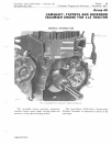
INST
ALLTNG
TAPPET
S AND
CAMSHAFT
Install
lift
ers
in
guides
.
It
is
go
od
practice
to
reinstall
lifter
in
sam
e
gui
de
fro
m
which
it
wa
s
r
emove
d.
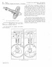
Install
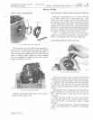
camshaft.
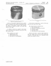
Match
chamfered
ge
ar
tooth
on
cra
nkshaft
ge
ar
with
mark
and
hobbing·
hole
on
camshaft
gear,
Figure
35.
Install
go
v
er
nor
spool
on
gov
e
rnor
gear
shaft.
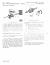
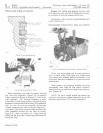
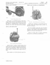
Fig.
36-l
n
stoll
in
g
Cylinder
Co
ver
Apply
oil
to
crankshaft
and
ca
mshaft
bea
r-
in
gs.
Install
new
cylinder
cove
r
gas
ket
on
cy
lin-
d
er
block.
Us
e
dowels
in
cyl
ind
er
bloc
k
to
kee
p
ga
sk
et
position
ed.
Remove
breaker
po
ints
and
push
rod
or
remov
e
box
cover
a
nd
hold
breaker
po
int
s
open.
Move
breaker
po
int
p
ush
r
od
t
owa
rd
points
to
prevent
dama
ge
to
pu
s h r
od
when
cy
lin-
d
er
c
over
is
installed.
Tu
rn
go
ve
rnor
rod
c
lock-
wise
(facing
end
of
shaft)
a
nd
install
cylinder
cover,
Figure
36.
Refer
to " T
orq
ue
Chart
."
in
S
ec
tion
10
for
cylinder
cove
r
bolt
t
orque
and
tighten
bolts
acc
o
rdingly.
L
itho
in
U.S. A.


