Tractors,
Lawn
and
Garden
-
110
and
112
Hydraulic
System
60
SM-
2059-
(Apr-
67)
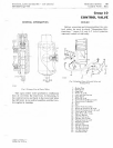
Control
Valve
10-7
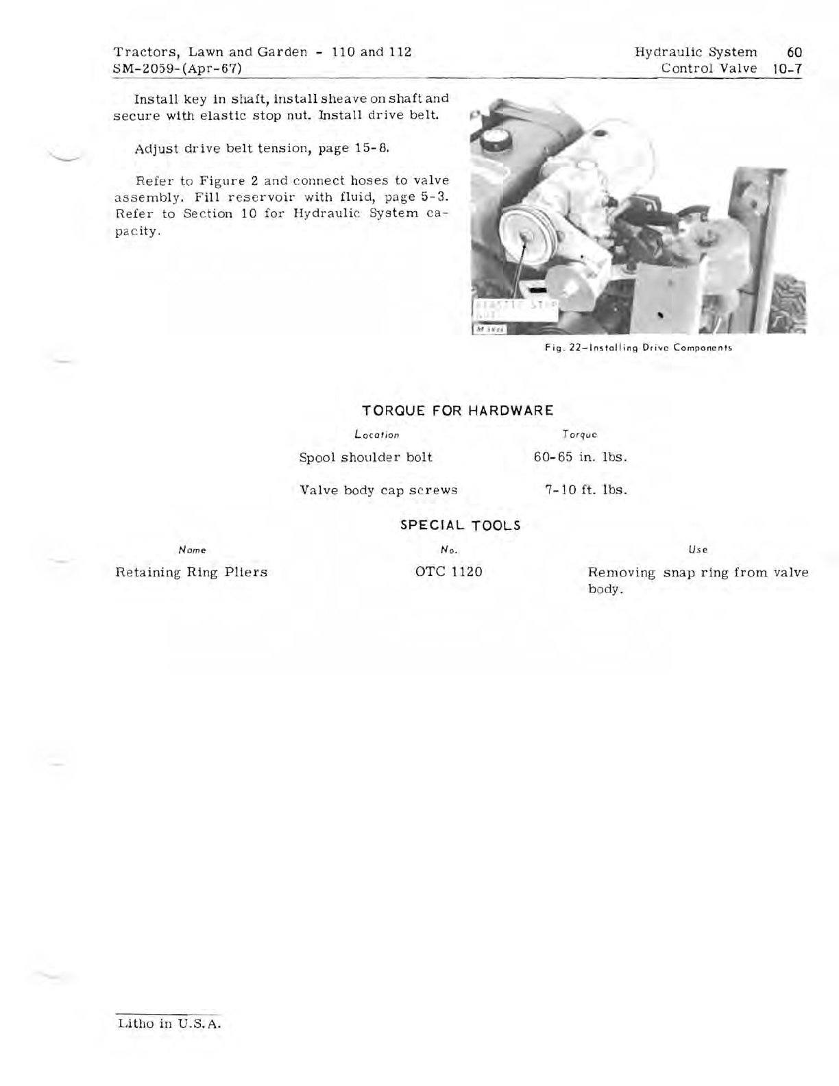
Install
key
in
shaft,
install
sheave
on
shaft
and
secure
with
elastic
stop
nut.
Install
drive
belt.
Adjust
drive
belt
tension,
page
15-8
.
Refer
to
Figure
2
and
c
onnect
hoses
to
valve
a
ssembly.
Fill
r es e
rvoir
with
flUid, pa
ge
5-
3.
Refer
to
Sec
tion
10
for
Hydrauli
c
System
ca-
p
ac
ity.
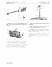
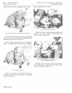
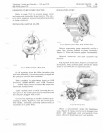
Fig.
22-lnslolling
Drive
Components
TORQUE
FOR
HARDWARE
Location
Spool
shoulder
bolt
Torque
60-65
in.
lbs.
Valve
body
cap
screws
7-10
ft.
lbs.
Nome
Retaining
Ring
Pliers
SPECIAL
TOOLS
No
.
OTC
1120
Us e
Removing
snap
ring
from
valve
body.
Litho
in
U.S.A.


