\:
0
'I
d(
-
~'"
Tr
actors,
Lawn
and
Garden
- 110
and
112
Power
Train
50
S
M-2059-(Apr-67)
3-Speed
Transaxle
15- 7
OPENING
TRANSAXLE
M 5 J'
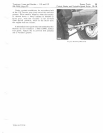
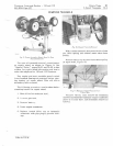
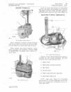
Fig.
IS-Remo
v
ing
Case
Screws
Place
transaxle
in
bench
or
stand
vertically
with
socket
head
cap
screws
up.
Remove
eight
scre
ws,
Figure
15.
Leave
dowel
pins
in
place.
While
holding
case
halves
together.
invert
entire
transaxle
and
reposition
in
bench.
THIS
IS
IMPORTANT.
Transaxle
cover
must
be
re-
moved
first.
1101
5618
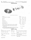
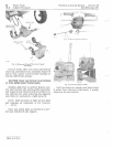
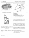
Fig.
16
-
Removing
Casc
Drive
out
dowel
pins.
Grasp
the
brake
s
ha
H
with
the
left
hand
and
transaxle
cover
with
the
right
hand.
Lift
case
Slowly
and
shake
lightly
so
all
loose
parts
remain
in
lower
case,
Figure
16.
RE MOVING
INTERNAL
COMPONENTS
IrE
l'.
t
AL
"
"n
tXl[
\1
I.
,
,'
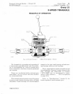
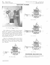
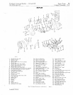
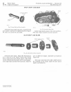
Fig.
17-Gear
Removal
Sequence
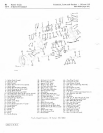
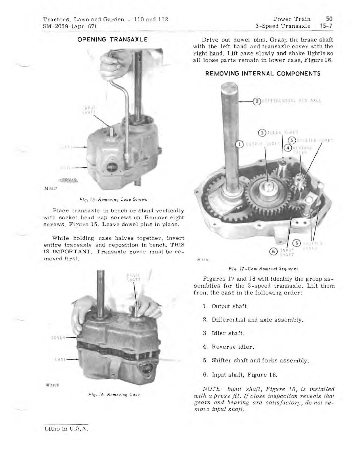
Figures
17
and
18
will
identify
the
group
as-
semblies
for
the
3-speed
transaxle.
Lift
them
from
the
case
in
the
following
order:
1.
Output
shaft.
2.
Differential
and
axle
assembly.
3,
Idler
shaft.
4.
Reverse
idler,
5.
Shifter
shaft
and
forks
assembly.
6.
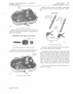
Input
shaft,
Figure
18,
NOTE:
Inpu.t
shaft,
Figure
1
B,
is
installed
with
a
press
fil.
If
clos
e
inspection
re
v
eals
thai
gears
and
bearing
are
satisfactory,
do
nol
r e-
rno'
lle
input
shaft.
Litho
in
U.S.A.


