Tractors,
Lawn
and
Garden
-
110
3nd
112
Electrical
System
40
SM
-2059-
(Apr-67)
Ignition
System
10-
15
Co
il
polarity
is
important
because
incorrect
polarity
will
r e
quil'e
4000-
8080
volts
mOl"e
to
fire
th
e
spark
plug.
One
method
to
che
ck
po-
l
arity
is
to
connect
the
negative
lead
of
a
volt
meter
to
the
spark
plu£r
termin
'
ll.
Wi-:h
engine
running,
momentaril
y
touch
positive
volt-
m
eter
le
ad
to
a g'ood
ground.
Th
e
co
il
polarity
is
cor
-
rect
if
the
meter
reads
up
scale.
!\nothel"
method
is
to
hold
the
spark
p
lu
g-
high
tens
i
oa
wi
re
a
bout
1/ 8
inch
from
the
spa
rk
plug,
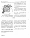
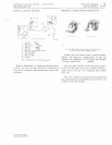
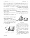
Insert
lea
d
po
int
of
a
wooden
pencil
in"
spark,
Figure
31.
Spark
should
flare
and
turn
orange
on
plug
side
of
pencil
lead
if
polarity
is
correct
. A
loss
of
eng
ine
powel'
is
also
noticed
when
the
co
il
poLlrity
is
incorr
ec
t.
Refer
to
illustrati
ons
in
Group
5
for
proper
el
ectrica
l
connections.
ADJUSTING
NE
U
TRAL-START
SWITCH
AND
BRAC
KET
Before
attempting
to
make
any
switch
01
'
bracket
adjustments,
check
the
neutral-start
bracket
for
ex
c
essive
l
ooseness
at
fork
pivot.
Also
c
heck
condition
of
dimple
on
und
erside
of
fo
rk.
Replace
bracket
if
necessary.
Continued
usage
of
the
tractor
s
hiIt
er
lever
will
cause
the
neutral-start
switch
to
wear
and
loosen,
making
switc
h
adjustment
n
ecessary.
Oc-
casionally,
a
neutral-start
switch
is
r
eplacedor
is
bypass-wired
even
though
a few
simple
ad-
justments
woule!
fix
it.
Before
replacing
a
switch,
follow
the
adj
us
tment
procedu
re
des
c
ri
bed
he
1'0
fOl"
110
and
112
Tra
ct
ors
.
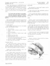
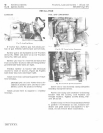
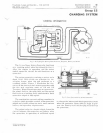
Fig,
32-
Te
s t
er
Conncc,cd
to
Switch
Ter
minals
110
Tr
octors
( ·
1500
0)
There
are
two
adjustments
whic
h
are
im-
portant
so
that
the
n
eut
r al
start
switch
will
op-
erate
as
designed,
whenever
the
shift
le
vel'
is
placed
into
nc:utral
to
complete
the
engine
crank
-
in
g-
circuit.
To
adjust
neutral
start
switch
3nd
bra
c
ket,
connect
a ('
untinu
ity
tester
to
switch
terminals,
FiQ;ure 32.
1.
Position
shift
l
evl
'
l'
so
that
dimple
in
und
e r
side
of
fork
plate
is
above
or
touching
switch
plung
·e
r.
Loosen
jam
nut
and
turn
switch
inward
until
continuity
is
observed
on
meter.
Th
en
turn
sw
it
ch
barrel
1/4
turn
c
lockwise
anc!
ti~hten
jam
nut.
2.
Mov
e
shift
lever
up
ancl
down
in
neutral
po
-
sition.
If
dimple
in
underside
of
fork
does
not
contact
plungc
!
r,
100sl'I1
both
swit
ch
bracket
screws
and
move
iJracket
until
dimpl2
in
lork
contacts
plung
e
r.
Tighten
cap
screws
firmly.
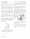
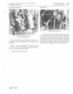
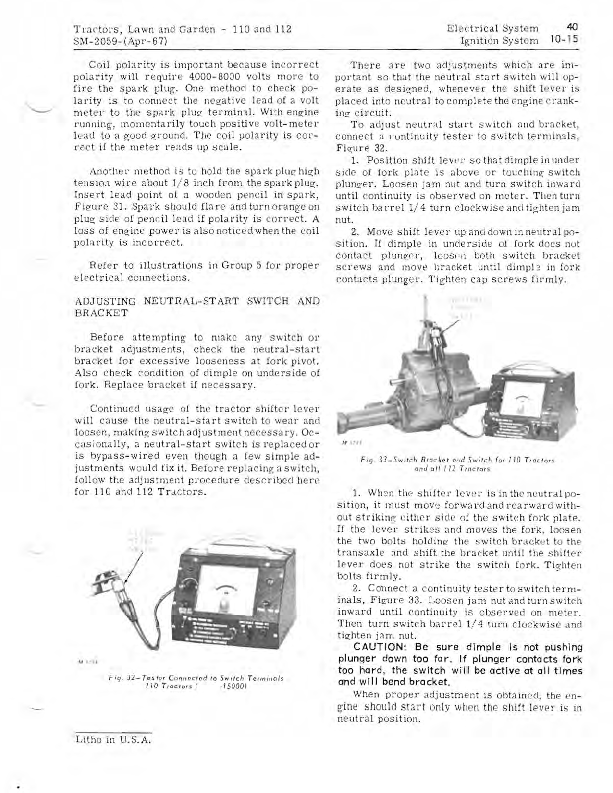
Fig,
33-Switch
B r
ocket
and
Switch
for
110
Traclors
and
0/1 T
12
Tractors
1. Wh:'n
the
shifter
l
ever
is
in
the
n
eutl
"
al
po-
Sition,
it
must
mov'~
forward
and
rearward
with-
out
strikin
g:
l'ithcr
side
of
the
switch
fork
plate.
If
the
l
ever
strikes
and
moves
the
fork
,
loosen
the
two
bolts
holding
the
switch
bracket
to
the
trans
ax
l e :
md
shift
the
bracke
t
until
the
shifter
l
ever
does
not
str
ik
e
the
switch
fork.
Ti
e.;hten
bolts
firmly.
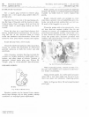
2. C011l1ect a
continuity
tester
to
switch
term-
inals,
Figure
33.
Loosen
jam
nut
and
turn
switeh
inward
until
continuity
is
observed
on
meter.
Then
turn
switch
barrel
1/ 4
turn
clo
c
kwise
and
tighten
jam
nut.
CAUTION:
Be
sure
dimple
Is not pushing
plunger down too
for.
If
plunger contacts
fork
too hard, the switch
will
be
active
at all
times
and
will
bend
bracket.
When
proper
adjus
tm
ent
is
obtained,
the
en-
gine
should
start
only when
the
shift
lever
is
in
neutr
al
pOSition.
Litho
in
U.S.A.


