Power
Train
SO
Tractors,
Lawn
and
Garden
-
110
and
112
SM
-2059-(Apr-67
)
Clutch,
Brake
and
Variable
Sp
e
ed
Drive
10-17
M l
if
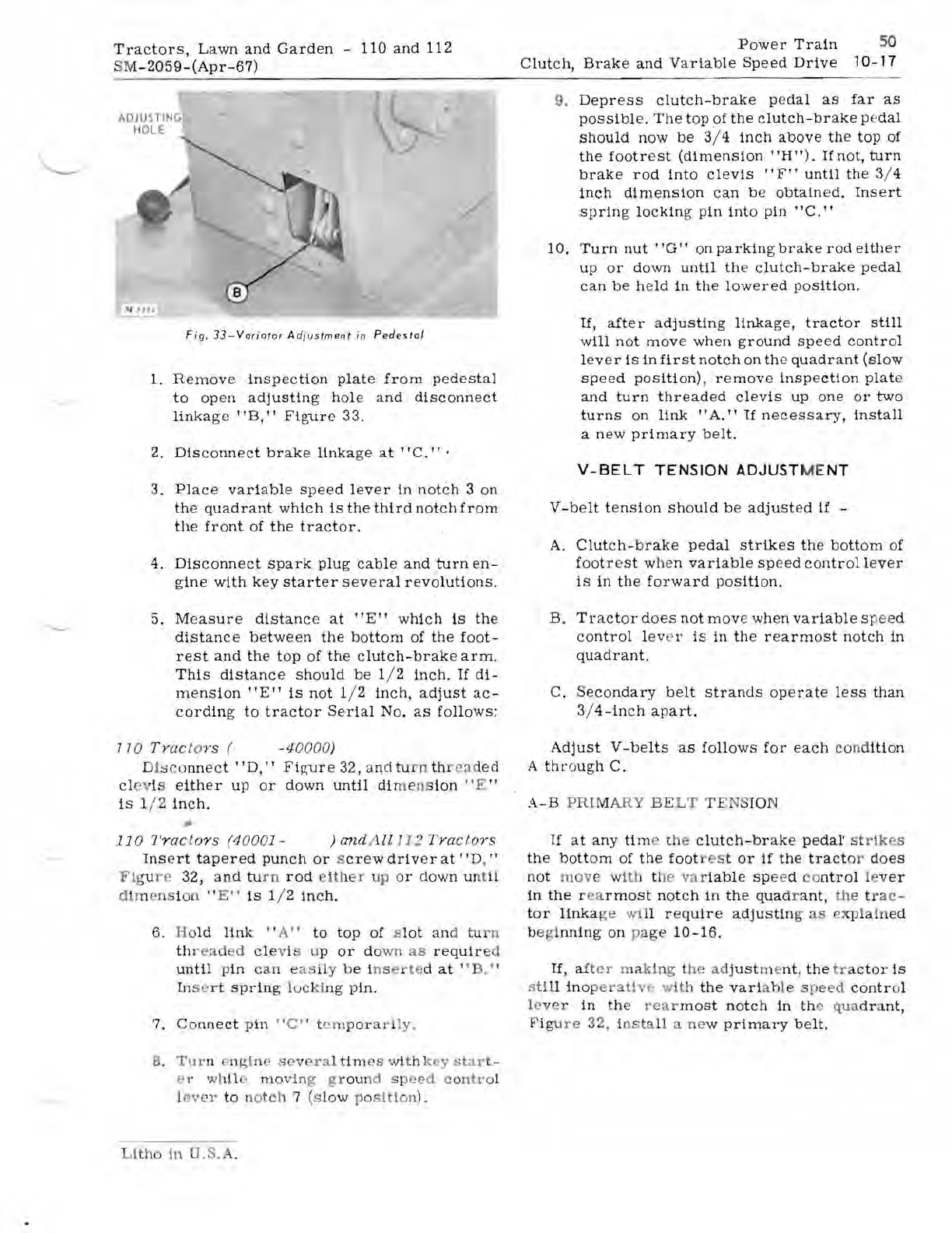
Fi
g.
33-V
or
ioto
r A dj
ustm
e
nt
in
Pedestal
1.
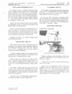
Remove
insp
e
ction
plate
from
ped
e
stal
to
open
adjusting
hole
and
disconnect
linka
ge
lIB, I I
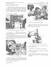
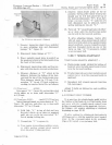
Figure
33.
2.
Dis
c
onn
e
ct
brake
linkage
at
"C."
,
3.
Place
variable
speed
lever
in
notch
3
on
the
quadrant
which
is
the
third
notch
from
th
e
front
of
the
tractor.
4.
Dis
c
onnect
spark
plug
cable
and
turn
en-
g
ine
with
key
starter
s e
veral
revolutions.
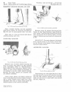
5. Me
asur
e
distance
at
"E"
which
is
the
distance
bet
w
een
the
bottom
of
the
foot-
rest
and
th
e
top
of
the
clutch-brake
arm.
This
distanc
e
should
be
1/ 2
inch.
If
di-
mension
"E"
is
not
1/ 2
inch,
ad
j
ust
ac-
cording
to
tractor
Se
rial
No.
as
follows:
n o T
mct
or s ( -
4000
0)
D
isco
nne
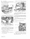
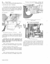
ct lID, I I
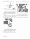
Figure
32, and
tu
rn
th
r
ea
de
d
cl
ev
i s
either
up
or
down
until
di
mens
ion
"E
"
is
1/ 2 i
nch,
.,.
11
0
Trac
to
rs
(40001 -
)
an
d A
ll
112
T m c t
or
s
Ins
e
rt
tapered
punch
or
s
crew
driv
er
at
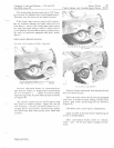
lI
D, "
Fig
u
re
32,
an
d
tu
rn
rod
ei
th
r up or
down
un
ti
l
d
im
ens i
on
" E "
is
1/ 2
in
ch.
6. Ho
ld
lin
k " A"
to
top
of
s
lot
and
tur
n
th
r
ea
d d clevis up
or
do
wn
as
requir
ed
until
p
in
ca
n e
as
i
ly
be ins e r
te
d
at
"B
,"
In
se
rt
sprin
g
locki
ng
p
in.
7.
Co
nnect
p
in
"C"
t
em
po
ra
ril
"
8.
Tur
n
pngtne
seve
ra
l
ti
m
es
wit h k
ey
star
t -
r whl1 mo
vi
ng
gr
ou
nd
speed
co
ntr
ol
l
ever
to
n
ot
ch
7 (s
lo
w po
sition.
Litho
1n
U
,S.
A.
9.
Depress
clutch-brake
pe
dal
as
far
as
possibl
e.
The
top
of
the
c
lutch-brake
pe
dal
should
now
be
3/ 4
inch
above
the
top
of
the
footr
e
st
(dimension
"H").
If
not,
turn
brake
rod
into
cleviS
"F"
until
the
3/ 4
inch
dimension
can
be
obtain
ed.
Insert
sprin
g
locking
pin
into
pin
"C."
10.
Turn
nut
"G"
on
parkin
g
brake
rod
either
up
or
do
wn
until
th
e
clutch-brake
pedal
can
be
held
in
the
lowered
position,
li,
after
a
djusting
linkage,
tractor
still
will
not
mov
e
when
ground
speed
control
lev
e r
is
in
first
notch
on
the
quadrant
(slow
speed
position),
remove
inspection
plat
e
and
turn
threaded
cl
e
vis
up
one
or
two
turns
on
link
"A."
If
necessary,
install
a
new
primary
belt.
V-BELT
TENSION
ADJUST ME
NT
V
-belt
tension
should
be
adjust
ed
if
-
A.
Clutch-
br
ake
pedal
strikes
th
e
bottom
of
footr
e
st
when
variable
sp
e
ed
control
lever
is
in
the
forward
position.
B.
Tract
or
does
not
mov
e
wh
en
variable
s
pee
d
control
lev
e r
is
in
the
rear
most
notch
in
quadrant.
C.
S
econdary
belt
strands
op
e
rate
le
ss
than
3/
4-inch
apart.
Adjust
V
-belts
as
follows
for
each
con
d
ition
A
th
r
CJtlgh
C.
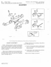
A-B
PRI
M
ARY
BE
LT
TENS
IO
N
If
at
any
tim
e
the
clutch-brak
e
pedal'
stri
kes
the
bott
om
of
the
foot
r
es
t
or
if
the
tract
or
do
es
no
t
move
with
tile
var
iabl
e s p
ee
d
co
ntrol
lev
er
in
the
r
ea
rmost
notch
in
the
qua
dr a
nt,
the
tr
ac-
tor
linka
ge
wi
ll
r e
quire
adjustin
g as e
xp
l
ain
ed
begi
nning
on
pa
ge
10-16.
If,
aft
er
ma
ki
ng t
he
adj
ust
me
nt
,
the
tr
a
ctor
is
s
ti
ll
in
o
per
ative
wit
h
the
vari
able s pe
ed
contr
ol
l eve r
in
the
rea
r
most
notc
h
in
the
qua
dr
nt,
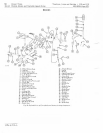
F
ig
ure
32,
in
ta
ll
ne
w
primary
b
elt
.


