Tractors,
Lawn
and
Garden
-
110
and
112
Power
Train
50
SM-2059-(Apr-67)
4-Speed
Transaxle
20-1 9
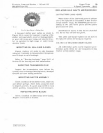
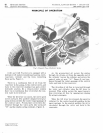
INSTALLING
AXLE
SUPPORTS
, .
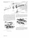
F
ig.
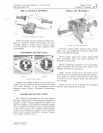
46-/nstal/ing
Axle
Supports
Install
O-rings
and
axle
supports
with
bear-
in
gs
as
shown
in
Figure
46.
Always
use
new
O-
r
ings,
Refer
to
"Bolt
Torque
Chart,"
page
10-4
of
Section
10
and
torque
support
bolts
accordingly.
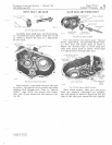
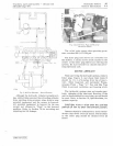
POS
ITIONI
NG
SHIFTER
FO
R
KS
Incorr
ect
Corr
ect
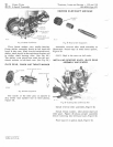
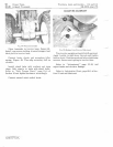
Fig .
47-Shirter
Forks
Inspect
th
e
shifter
forks
to
be
sure
they
are
aligned
and
in
neutral
position.
Failur
e
to
do
this
will
cause
damage
to
the
transmission
when
engaged
und
er
power.
(Compare
illustrations
above.)
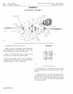
ASSEMBLING
SHIFTER
LEVER
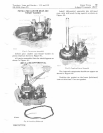
The
shifter
is
assembled
in
th
e o
rder
shown
in
Figure
19,
page
20-9.
When
assembling
shifter,
be
sure
rubber
seal
is
positioned
properly
in
shifter
housin
g. A
little
shellac
or
gasket
cement
will
be
helpful
to
prevent
incorrect
positioning
of
the
rubb
e r
seal
In
the
housing.
Ali
gn
housing,
keeper
and
spring
pin
in
shift
lever
a nd
plac
e
snap
ring
in
groove
In
shifter
housing.
Torque
cap
screws
to
120
in-lbs.
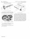
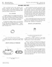
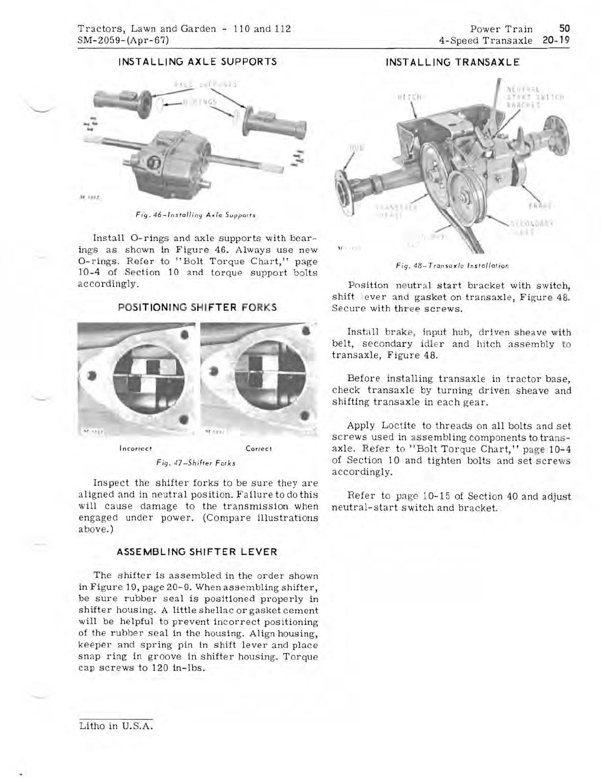
INSTALLING
TRANSAXLE
~t
· ,
It
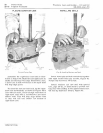
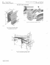
Fig
.
43-Transoxle
Installation
Position
ne
utr
al
start
bracket
with
swit
ch,
shift
:c
ver
and
gasket
on
transaxle,
Figure
48.
Secure
with
thr
e e
scr
e
ws.
Inst
a
ll
brak
, 'n
pu
t
hub,
dr
iv
en
sheave
with
belt,
secondary
idl
l'
and
hitch
assembly
to
transaxle,
Figure
48.
Before
installing
transaxle
in
tractor
base,
check
transaxle
by
turning
driven
sheave
and
shifting
tr
ansa
xle
in
each
gea
r.
Apply
Lo
c
tite
to
threads
on
all
bolts
and
set
screws
used
in
as
sem
b
ling
components
to
tra
ns-
ax
le. R
efer
to
"Bo
lt
T
orque
Chart,"
pa
ge
10-4
of
Section
1 0
and
tight
en
bolts
a
nd
set
sc
re
ws
accordingly.
Refer
to
page
1
0-15
of
Section
40
and
adjust
neutral-start
switch
and
bracket.
Litho
in
U.S.A.


