60
Hydraulic
System
Tractors,
Lawn
and
Garden
-
110
and
112
15-6
Pump
SM-2059-(Apr-67)
ASSEMBL Y
-Continued
"
.•
r
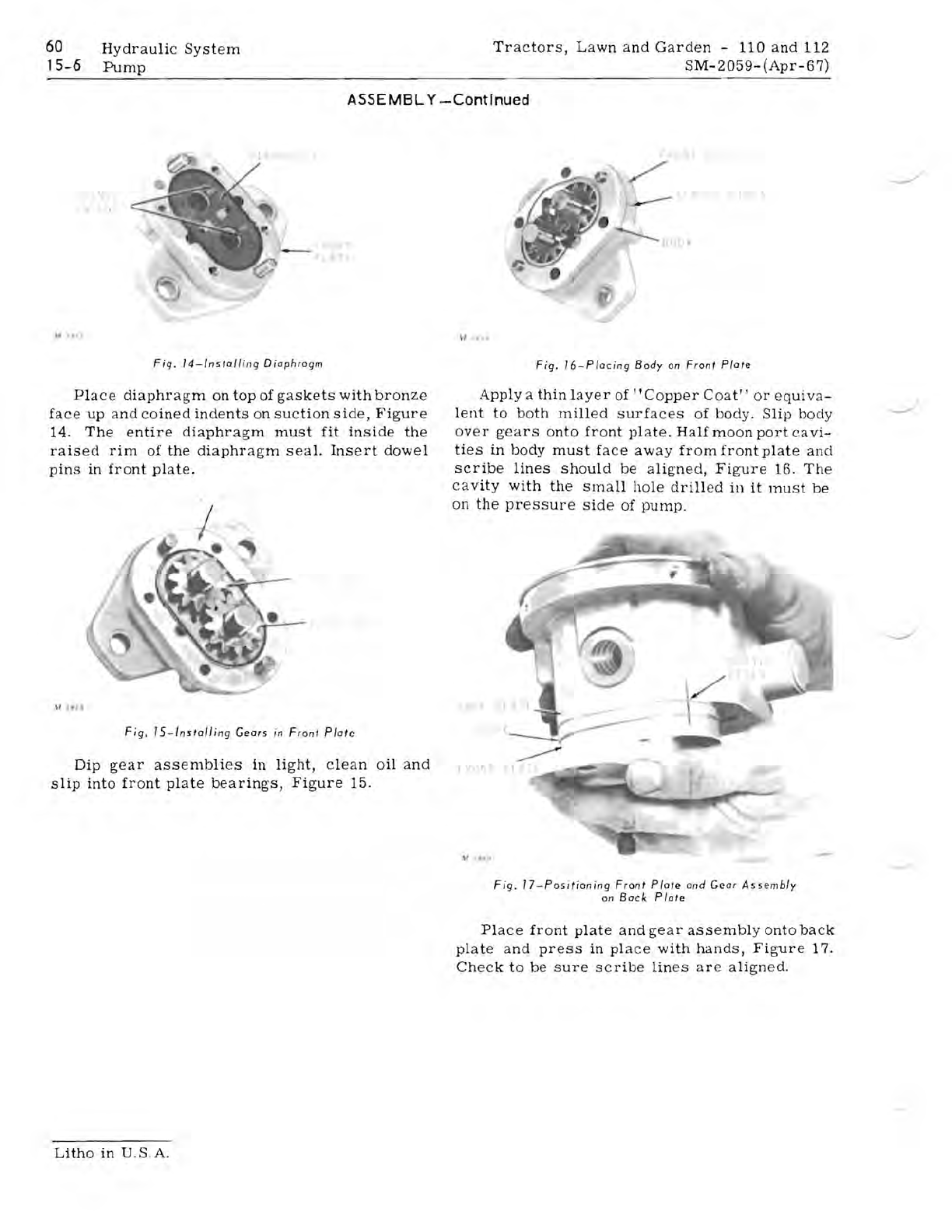
Fig
.
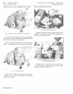
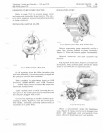
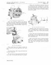
14-lnstal/
i
ng
Diaphragm
Place
diaphragm
on
top
of
gaskets
with
bronze
face
up
and
coined
indents
on
suction
side,
Figure
14.
The
entire
diaphragm
must
fit
inside
the
raised
rim
of
the
diaphragm
seal.
Insert
dowel
pins
in
front
plate.
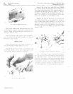
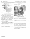
Fig.
IS-Installing
Gears
in
Front
Plate
Dip
gear
assemblies
in
light,
clean
oil
and
slip
into
front
plate
bearings,
Figure
15.
"
..
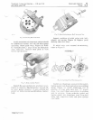
Fig.
16-Plocing
Body
on
Front
Plate
Apply
a
thin
layer
of
"Copper
Coat"
or
equiva-
lent
to
both
milled
surfaces
of
body.
Slip
body
over
gears
onto
front
plate.
Half
moon
port
eavi-
ties
in
body
must
face
away
from
front
plate
and
scribe
lines
should
be
aligned,
Figure
16.
The
cavity
with
the
small
hole
drilled
in
it
must
be
on
the
pressure
side
of
pump.
',T
..,
'I'
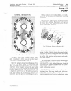
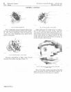
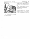
Fig.
17-Positioning
Front
Plate
and
Gear
Assembly
on
Bock
Plate
Place
front
plate
and
gear
assembly
onto
back
plate
and
press
in
place
with
hands,
Figure
17.
Check
to
be
sure
scribe
lines
are
aligned.
Litho
in
U.S.A.


