20
Engine
Tractors,
Lawn
and
G
arde
n -
110
and
112
15-10
Piston.
Crankshaft
and
Flywheel
-
Kohler
SM-2059-(Apr
-67}
"
..
I
II',
1 'fI,
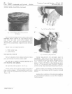
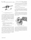
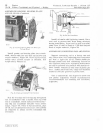
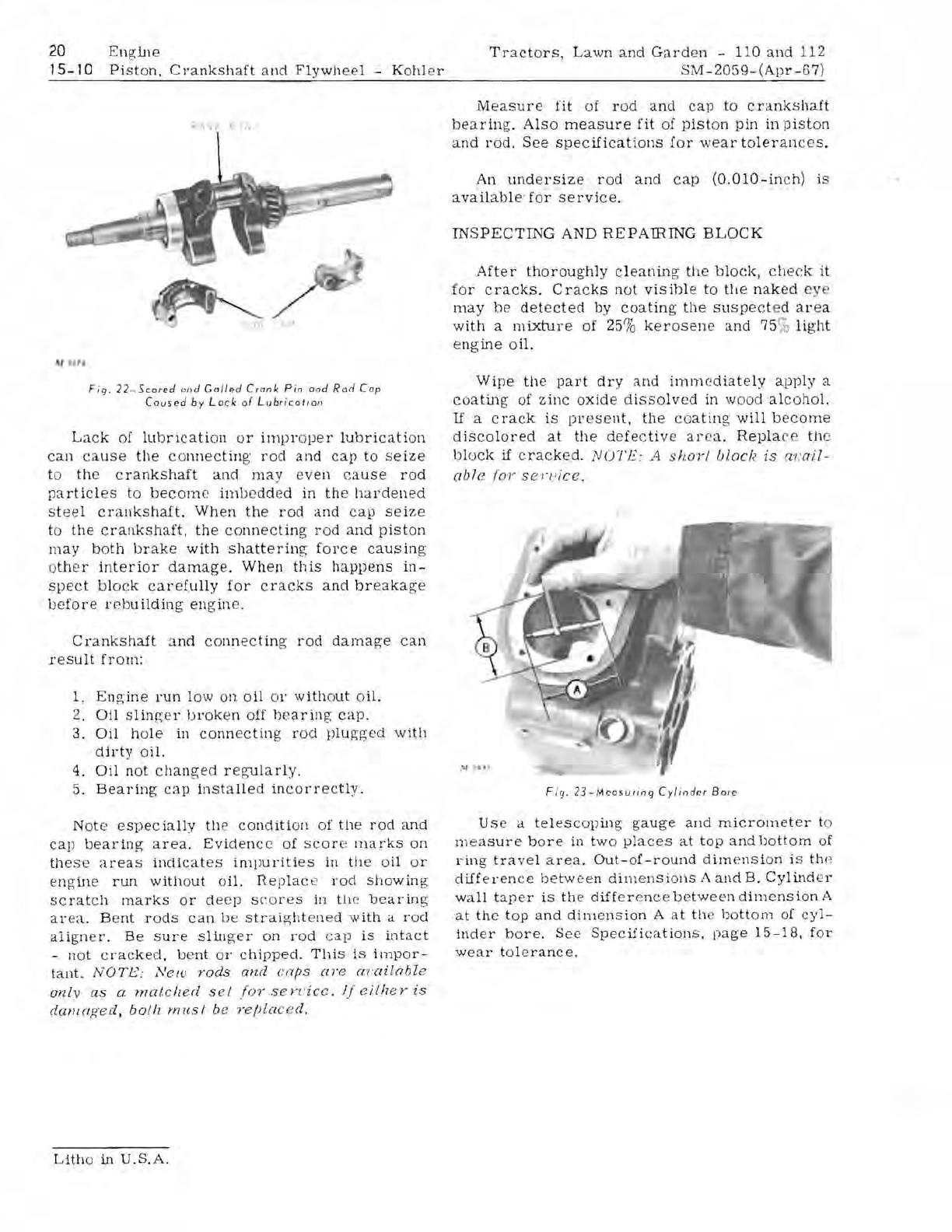
Fig.
22 -
Scared
ond
Galled
Crank
Pin
and
Rod
Cap
C
ause
d
by
Lo
ck
01
Lubricat
ion
Lack
of
lubrication
or
irnpr
oper
lubricati
on
ca
n
ca
use
the
connecting
rod
and
cap
to
seize
to
the
crankshaft
and
may
even
cause
rod
particles
to
become
imb
edded
in
th
e
hardened
steel
crankshaft.
When
the
rod
and
cap
seize
to
the
crankshaft,
the
connecting
rod
and
piston
may
both
brake
with
shattering
force
causing
o
th
er
interior
damage.
When
this
happens
in-
spect
block
carefully
for
cracks
and
breakage
be
fore
r
eb
uilding
engin
e.
Crankshaft
:md
conne
c
tin
g
rod
damage
can
result
from:
1.
Engine
run
low
on
oil
0
1'
w
ith
o
ut
oil.
2.
Oil
Slinger
broken
off
bearing
cap
.
3.
Oil
hole
in
conn
ecti
ng
r
od
plugged
with
dirty
oil.
4.
Oil
not
changed
regularly.
5.
Bearing
cap
installed
incorrectly.
Not
e
espec
ially
the
condition
of
the
rod
and
cap
bearing
area.
Eviden
ce
of
sco
r e
marks
on
these
areas
indicates
impurities
in
th
e o
il
or
eng
ine
run
without
oil.
TIeplac
e
rod
showin
g
scratch
marks
or
de
ep
scores
in tile
bearing
area.
Be
nt
rods
can
be
straight
en
ed
with
a
rod
aligner.
Be
Sure
slinger
on
rod
cap
is
intact
-
not
cracked,
bent
or
chipped.
This
is
impor-
tant.
NOTE:
Ne/U
rods
and
caps
are
cn-ailable
only
as
a
matched
sel
forsen
:
icc.
IjciLheris
dW)1
(l.£{e
d,
bolh
must
be ?'e/)laced.
Measure
fit
of
r
od
and
cap
to
crankshaft
bearing.
Also
measure
fit
of
piston
pin
in
piston
and
r
od
.
See
specifications
ior
wear
toleranc
es
.
An
undersize
rod
and
cap
(O
.OlO-in
ch)
is
available
·
for
service.
INSPECTING
AND
REPAffiING
BLOCK
After
thoroughly
cleaning
the
bloek,
check
it
for
cracks.
Cracks
not
visible
to
the
nak
ed
ey
may
be
det
e
cted
by
coating
the
suspect
ed
area
w
ith
a
mixture
of 25%
kerosen
e
and
75
%
light
e
ngine
oil.
Wipe
the
part
dry
and
imm
e
diately
apply
a
coating
of
zinc
oxide
dissolved
in
wood
alcohol.
U a c
rack
is
present.
th
e
coa
ting
will
become
discolored
at
the
defective
ar
e
a.
Repla
th
e
block
if
crac
ked
.
NOTE
; A
shoyl
bloch
is
av
ail-
abl
e
/01'
sen
'
ice.
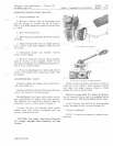
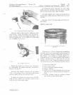
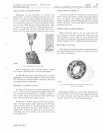
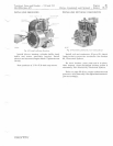
Fig.
23-Mcasuring
Cyl
inder
Bore
Us
e a
telescoping
gauge
and
micrometer
to
m
ea
sure
b
ore
in
two
places
at
top
and
bottom
of
ring
tra
ve
l
ar
ea.
Out-oi-round
dimension
is t1w
difference
between
dimensions
A
and
B.
Cylind
e l'
wall
tap
er
is
the
differ
ence
between
dimension
A
at
th
e
top
and
dim
e
nsion
A
at
th
e
bottorn
of
cyl-
ind
er
bore.
See
SpeCifications.
page
15-18,
for
wear
tol
era
nce.
Lith
o
in
U.S.A.


