60
Hydraulic
System
Tractors,
Lawn
and
Garden
-
110
and
112
5-2
General
Information
SM-2059-(Apr-67)
PRINCIPLE
OF
OPERATION
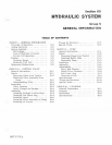
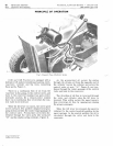
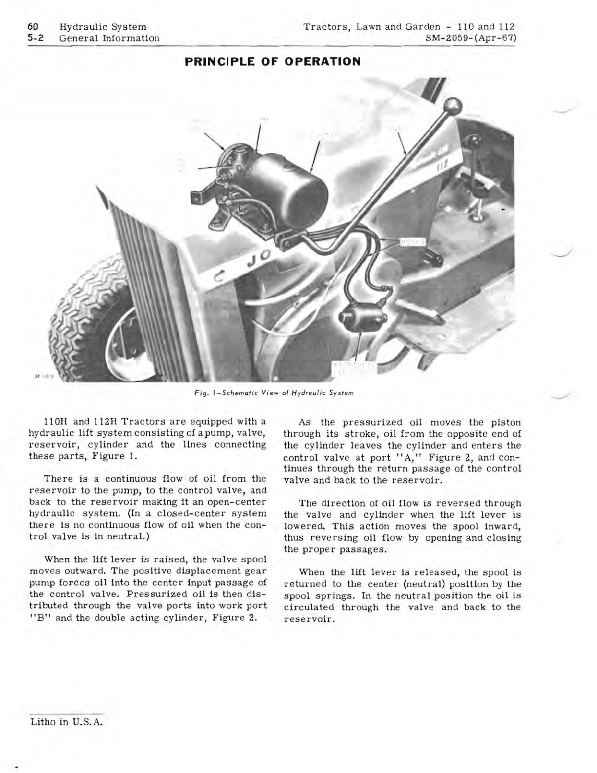
Fig.
I-Schemat
ic
View
01
Hydraulic
System
110H
and
112H
Tractors
are
equipped
with
a
hydraulic
lift
system
consisting
of
a
pump,
valve,
reservoir,
cylinder
and
the
lines
connecting
these
parts,
Figure
1.
The
re
is
a
continuous
flow
of
oil
from
the
reservoir
to
the
pump,
to
the
control
valve,
and
back
to
the
reservoir
making
it
an
open-center
hydraulic
system.
(In a
closed-center
system
there
is
no
continuous
flow
of
oil
when
the
con-
trol
valve
is
in
neutral.)
When
the
lift
lever
is
raised,
the
valve
spool
moves
outward.
The
positive
displacement
gear
pump
forces
oil
into
the
center
input
passage
of
the
control
valve.
Pressurized
oil
is
then
dis-
tributed
through
the
valve
ports
into
work
port
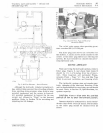
"B"
and
the
double
acting
cylinder,
Figure
2.
As
the
pressurized
oil
moves
the
piston
through
its
stroke,
oil
from
the
opposite
end
of
the
cylinder
leaves
the
cylinder
and
enters
the
control
valve
at
port
"A,"
Figure
2,
and
con-
tinues
through
the
return
passage
of
the
control
valve
and
back
to
the
reservoir.
The
direction
of
oil
flow
is
reversed
through
the
valve
and
cylinder
when
the
lift
lever
is
lowered.
This
action
moves
the
spool
inward,
thus
reversing
oil
flow
by
opening
and
closing
the
proper
passages.
When
the
lift
lever
is
released,
the
spool
is
returned
to
the
center
(neutral)
position
by
the
spool
springs.
In
the
neutral
position
the
oil
is
circulated
through
the
valve
and
back
to
the
reservoir.
Litho
in
U.S.A.


