60
Hydraulic
System
Tractors,
Lawn
and
Garden
-
110
and
112
20-2
Cylinder
SM-2059-(Apr-67)
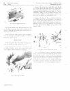
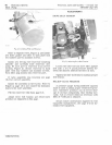
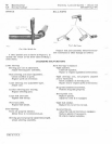
REMOVAL
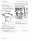
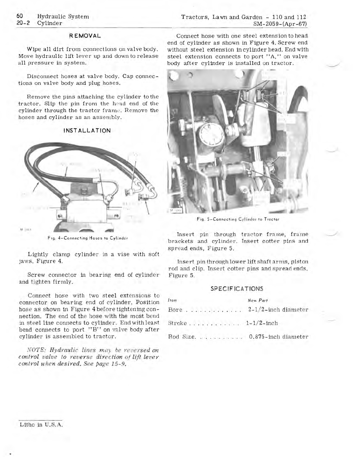
Connect
hose
with
one
steel
extension
to
head
end
of
cylinder
as
shown
in
Figure
4.
Screw
end
Wipe
all
dirt
from
connections
on
valve
body.
without
steel
extension
in
cylinder
head.
End
with
Move
hydraulic
lift
lev
e r
up
and
down
to
release
steel
extension
connects
to
po
rt"
A,"
on
valve
all
pressure
in
system.
body
after
cylinder
is
installed
on
tractor.
Disconnect
hoses
at
valve
body.
Cap
connec-
tions
on
valve
body
and
plug
hoses.
Remove
the
pins
attaching
the
cylinder
to
the
tractor.
Slip
the
pin
from
the
h0ad
end
of
the
cylinder
through
the
tractor
fram
l';
.
Remove
the
hoses
and
cylinder
as
an
assernbly.
I NST
ALLA
TION
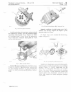
Fig.
4-Connccl
ing
Hoses
10
Cyl
i
nder
Lightly
clamp
cylinder
in
a
vise
with
soft
ja
ws ,
Figure
4.
Screw
connector
in
bearin
g
end
of
cylin
de r
and
tig
hten
firmly.
Co
nn
e
ct
hose
with
two
steel
ext
en
s i
on
s
to
conn
ec
tor
on
bearing
end
of
cy
linder.
Position
ho
se
a s
hown
in
F
igur
4
be
fo
re
ti
{;
ht
e
ning
con-
nection.
The
end
of
th
e l o
se
wi
th
the
most
bend
in s e
el
line
connect
s
to
cylind
r . End
with
leaHt
bend
conn
c
ts
to
port
"B"
on
va
l
ve
body
after
cylind
e r
is
assembled
to
tra
o
r.
N
OT
E:
Hydvaulic l
ine
s m ay be yet'e ysed on
control
valv
e to -r
ever
se
dir
ction
of
lift
Zeller
control
when
desired.
See page
lS-9.
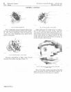
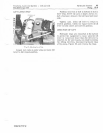
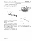
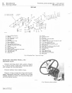
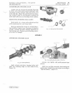
Fig
.
5-Conneclin
g Cy
lin
d
er
to
Traclor
Ins
e
rt
pin
throu
gh
tr
act
or
fr
a m
e,
fr a m e
brackets
an
d
cylind
r .
Insert
cott
er
pins
and
spr
ead
en
ds,
F
igure
5.
Ins
e
rt
pin
throu
gh
lower
lift
s
haft
arms,
pi
s
ton
rod
and
clip.
Ins
e
rt
cot
te r
pin
s
and
sp
rea
d
nds,
Fi~r
e
5.
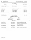
SP
EC
IF
ICAT
IONS
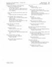
Irem
N ew
PorI
re
2-1
/
2-
in
ch
di
a met er
·
tr
oke
.
.......
...
.
I-l
i
Z-in
c h
R
od
S
ize.
. . . . . . . .
..
O.875-inch
dia
meter
Litho
in
U. . .


