60
Hydraulic
System
Tractors,
Lawn
and
Garden
-
110
and
112
10-4
Control
Valve
SM-2059-
(Apr-57)
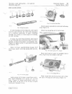
INSPECTION
VAL
VE
HOUSING
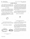
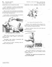
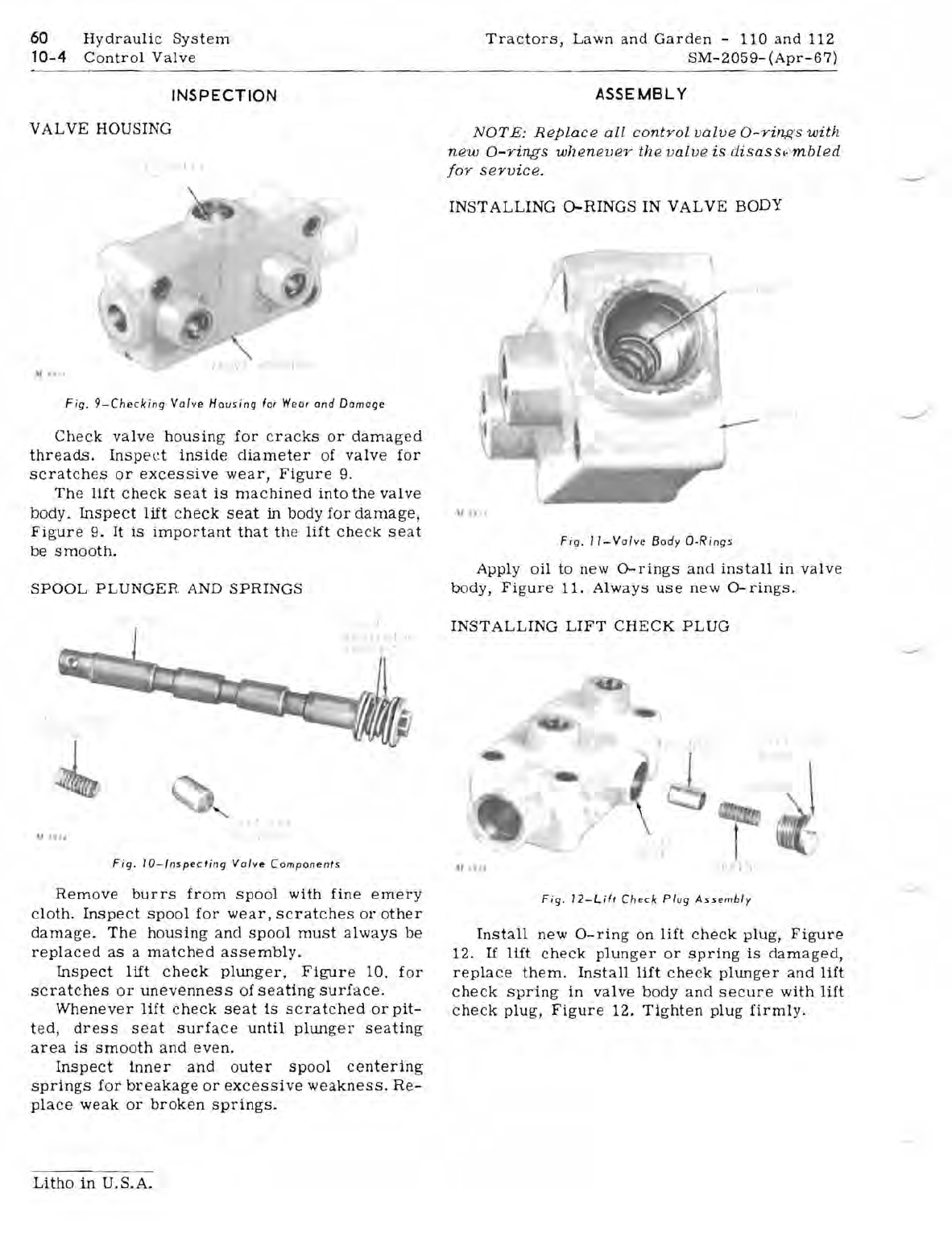
Fig.
9-Checking
Valve
Housing
fa,
Weo
,
and
Damage
Check
valve
housin
g
for
cracks
or
damaged
threads.
Inspect
inside
diameter
of
valve
for
scratches
or
excessive
wear,
Figure
9.
The
lift
check
seat
is
machined
into
the
valve
body.
Inspect
lift
check
seat
in
body
for
damage,
Figure
9.
It
is
important
that
the
lift
che
ck
seat
be
smooth.
SPOOL
PLUNGER
AND
SPRINGS
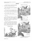
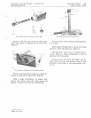
Fig
.
IO-lnspecting
Valvt!
Components
Remove
burrs
from
spool
with
fine
emery
cloth.
Inspect
spool
for
wear,
scratches
or
other
damage.
The
housing
and
spool
must
always
be
replaced
as
a
matched
assembly.
Inspect
lift
check
pitll1ger,
Figure
10,
for
scratches
or
unevenness
of
seating
surface
.
Whenever
lift
check
seat
is
scratched
or
pit-
ted,
dress
seat
surface
until
plunger
seating
area
is
smooth
and
even.
Inspect
inner
and
outer
spool
centering
springs
for
breakage
or
excessive
weakness.
Re-
place
weak
or
broken
springs.
Litho
in
U.S.A.
ASSEMBLY
NOTE:
Replace
all
control
valve
O-ri/1.{!,'S
with
new
a-rings
whenever
the
valve
is
disasst
:
mbled
jor
service
.
INSTALLING
O-RINGS
IN
VALVE
BODY
"
\l
h'
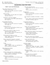
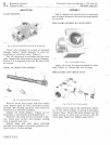
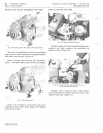
Fig.
II-Valve
Body
D-R
i
ngs
Apply
oil
to
new
O-rings
and
install
in
valve
body,
Figure
11.
Always
use
new
O-rings.
INSTALLING
LIFT
CHECK
PLUG
"
..
' f
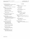
Fig.
12-Lift
Check
Plug
Assembly
Install
new
O-ring
on
lift
check
plug,
Figure
12.
If
lift
check
plunger
or
spring
is
damaged,
replace
them.
Install
lift
check
plunger
and
lift
check
spring
in
valve
body
and
secure
with
lift
check
plug
,
Figure
12.
Tighten
plug
firmly
.


