AIJD
WASHER
INPUT
SHAFT
BEAR!NG
Tractors
,
Lawn
a
nd
Garden
-
110
and
112
Power
Train
SO
SM-2059-(Apr-67)
4-Speed
Transaxle
20-13
INPUT
SHAFT
AND
GEAR
cuu
TE
.
BORE!)
)
PLI
E
M
j1/5
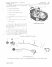
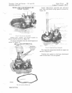
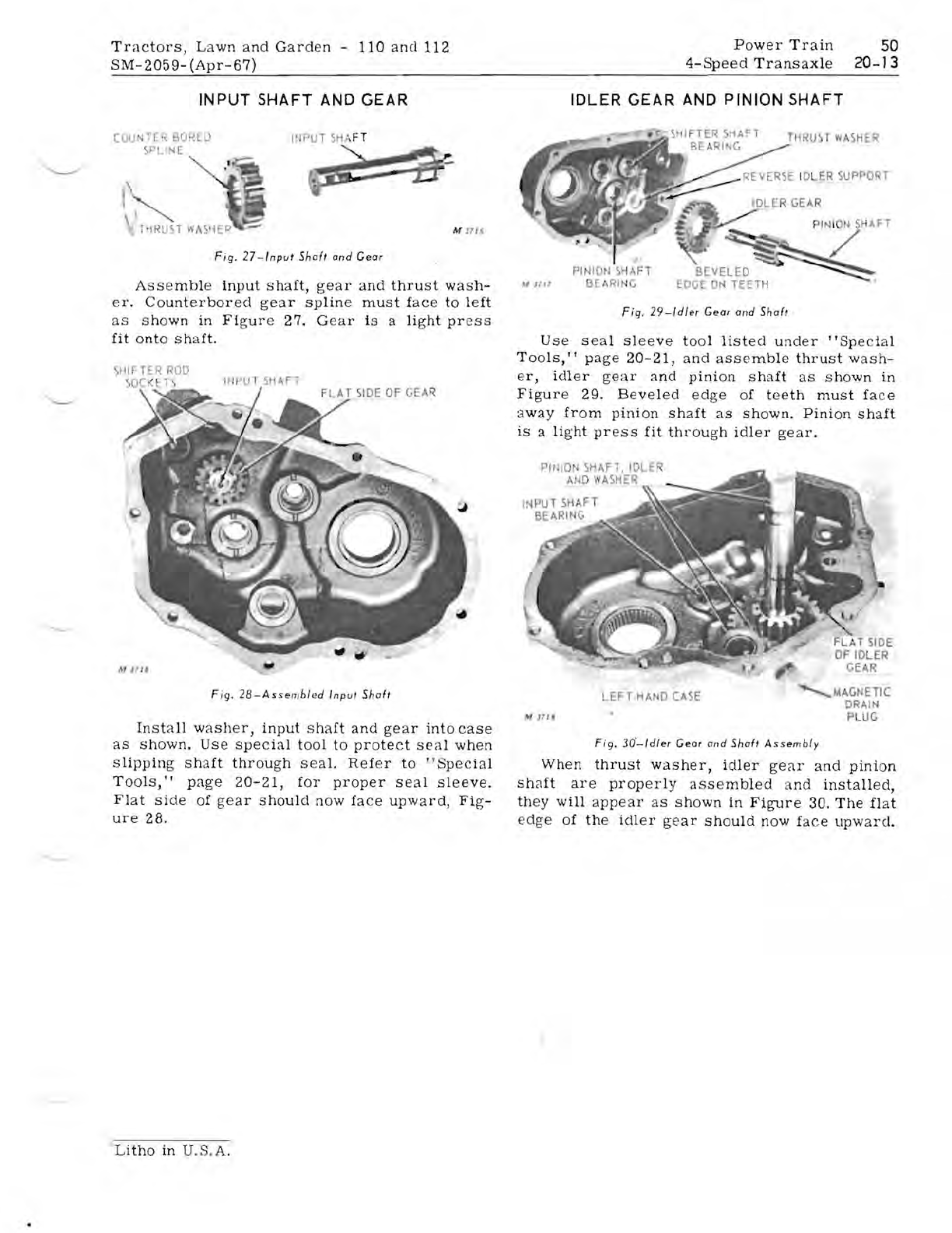
Fig
.
27-lnput
Shaft
and
Gear
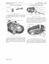
Assemble
input
shaft,
gear
and
thrust
wash-
er.
Counterbored
gear
spline
must
f
ace
to
left
as
shown
in
Figure
27.
Ge
ar
is
a
light
press
fit
onto
shaft.
SHIFTER
ROD
S
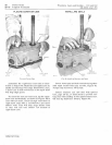
Fig.
28-Assembled
Input
Shaft
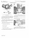
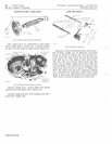
Install
washer,
input
shaft
and
gear
into
case
as
shown.
Us
e
special
tool
to
protect
seal
when
slipping
shaft
through
seal.
Refer
to
" S
pecial
Tools,"
page
20-21,
for
proper
seal
sleeve.
Flat
side
of
gear
should
now
face
upward,
Fig-
ure
28.
IDLER
GEAR
AND
PINION
SHAFT
THRUST
W
SHER
ER5
E IDl.ER
SUPPORT
P
IN
I
ON
SHAF
T
/
PINIO
I
SI-IAFT
M 1117 BE,\
RING
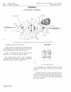
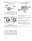
Fig.
29-ldler
Gear
and
Shaft
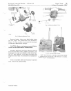
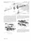
Use
seal
Sleeve
tool
listed
under
"Special
Tools,"
page
20-21,
and
assemble
thrust
wash-
er,
idler
gear
and
pinion
shaft
as
shown
in
Figure
29.
Beveled
edge
of
teeth
must
face
away
from
pinion
shaft
as
shown.
Pinion
shaft
is
a
light
pr
ess
fit
through
idler
gear.
PHilO
SHAFT,
IDLER
M
J7i!
~
MAGNETIC
LEFT
-H
AND
CASE
DRAIN
PL
UG
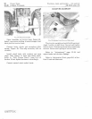
Fig.
30'-
ldler
Gear alld
Shaft
Assembly
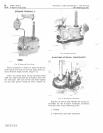
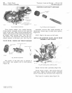
When
thrust
washer,
idler
gear
and
pll1lOn
shaft
are
properly
assembled
and
installed,
th
ey
will
appear
as
shown
in
Figure
30.
The
fl
at
edge
of
the
idler
gear
should
now
face
upward.
Litho
in U.S.
A.


