Tra
c
tors,
Lawn
and
Garden
-
110
and
112
Engine
20
SM
-2059-
(Apr-67)
Camshaft,
T
app2
ts
and
Governor
-
Tecumseh
40
-5
INSTALL
AT ION
INSTALLING
GOVERNOR
SHAFT
INS
TALLING
GOVERNOR
GEAR
AND
SPOOL
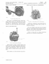
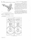
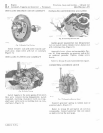
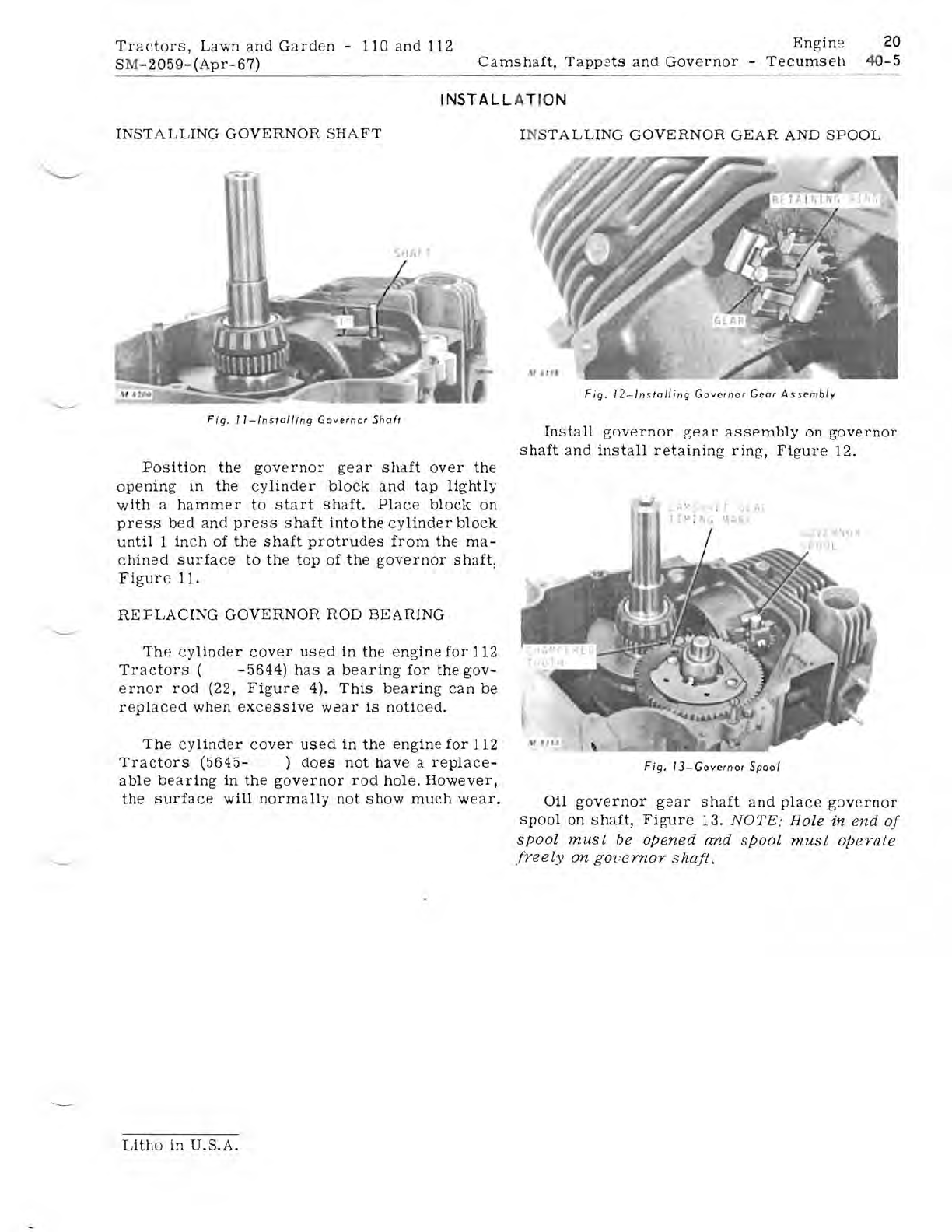
Fig.
II-Installing
Governor
Shoft
Position
the
governor
gear
shaft
over
the
opening
in
the
cylinder
block
and
tap
lightly
with
a
hammer
to
start
shaft.
Place
block
on
press
bed
and
press
shaft
into
the
cylinder
block
until
1
in
ch of
the
shaft
protrudes
from
the
ma-
chined
surface
to
the
top
of
the
governor
shaft,
Figur
e 11.
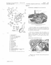
REPLACING
GOVERNOR
ROD
BEARING
Th
e
cylinder
cover
used
in
the
engine
for
112
Tra
c
tors
(
-5644)
has
a
bearing
for
the
gov-
ernor
roel (22,
Figure
4).
This
bearing
can
be
replaced
when
excessive
waar
is
noticed.
The
cylinder
cover
used
in
the
engine
for
112
Tractors
(5645-
)
does
not
have
a
replace-
a
ble
bearing
in
the
governor
rod
hole.
However,
the
surface
will
normally
not
show
much
wear.
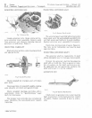
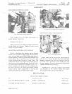
Fig.
12-lnsta/ling
Governor
Gear
A
ssembly
Install
governor
gear
assembly
on
governor
shaft
a
nd
install
retaining
ring,
Figure
12.
f'
L"
II'J(
;.>
L
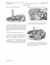
Fig.
13
-
Governor
Spool
011
governor
gear
shaft
and
place
governor
spool
On
shaft,
Figure
13.
NOTE:
Hole in
end
of
spool
must
be
opened
and
spool
must
opeYale
freely
on
goz'ernor
shaft.
Litho
in
U.S.A.


