50
Power
Train
Tractors,
Lawn
and
Garden
-
110
and
112
20-14
4-Speed
Transaxle
SM-2059-(Apr-67)
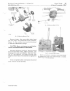
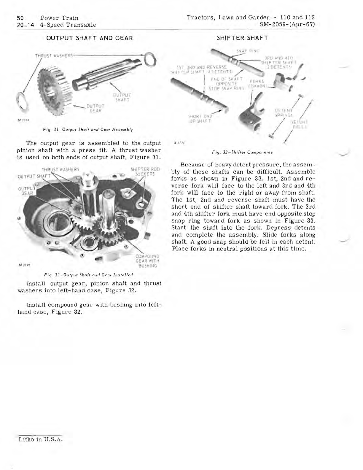
OUTPUT SHAFT
AND
GEAR
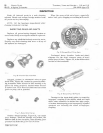
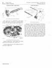
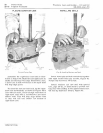
Fig
,
31-0ulpul
Shafl
and
Gear
Assembly
The
output
gear
is
assembled
to
the
output
pinion
shaft
with
a
press
fit.
A
thrust
washer
is
used
on
both
ends
of
output
shaft,
Figure
31.
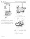
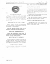
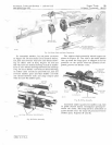
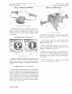
Fig
.
32-0Ulput
Shaft
and
Gear
Installed
Install
output
gear,
pinion
shaft
and
thrust
washers
into
left-hand
case,
Figure
32.
Install
compound
gear
with
bushing
into
left-
hand
case,
Figure
32.
SHIFTER SHAFT
!'
II
J or
...
/-f
~
UI'PD}i
, 1
OP
~
~p
,I
'.,
~
~'IORl
I"
ID
0F ,11:';:- 1
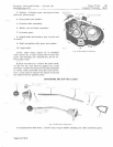
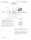
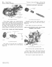
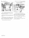
Fig.
33-Shifter
Components
Because
of
heavy
detent
pressure,
the
assem-
bly
of
these
shafts
can
be
difficult.
Assemble
forks
as
shown
in
Figure
33.
1st,
2nd
and
re-
verse
fork
will
face
to
the
left
and
3rd
and
4th
fork
will
face
to
the
right
or
away
from
shaft.
The
1st,
2nd
and
reverse
shaft
must
have
the
short
end
of
shifter
shaft
toward
fork.
The
3rd
and
4th
shifter
fork
must
have
end
opposite
stop
snap
ring
toward
fork
as
shown
in
Figure
33.
Start
the
shaft
into
the
fork.
Depress
de
tents
and
complete
the
assembly.
Slide
forks
along
shaft.
A
good
snap
should
be
felt
in
each
detent.
Place
forks
in
neutral
positions
at
this
time.
Litho
in
U.S.A.


