Tractors.
Lawn
and
Gard
en -
11
0
and
112
En::;ine
20
CiM-2059
-(Apr-67)
Piston,
Crankshaft
and
Flywheel
-
Kohler
15-13
INSTALLATION
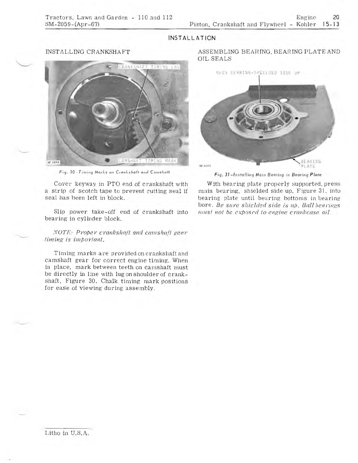
INST1\LLING
CRANK..SHAFT
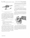
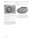
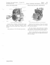
Fig.
30
-
Timing
Mark"
on
Crankshoft
and
Cams
haft
Cover
keyway
in
PTO
end
of
cr
ankshaft
with
a
strip
of
scotch
tape
to
prevent
cutting
seal
if
seal
has
been
left
in
block.
Slip
power
take-off
end
of
crankshaft
into
bearing-
in
cylinder
block.
NOT!,':
ProjJer
cyanks!w/t
and
ca7llsh{(ft
r;ear
liminr;
is
imjJortant.
T i
111
ing;
ma
rks
are
prov
ided
on
c
rankslJaft
and
camshaft
g-ear
for
co
rr
ec
t
eng
'
ine
tirninf(.
When
in
place,
mark
between
t
ee
th
on
camshaft
rnust
be
directly
in
line
with
lug
on
shoulder
of
cl
'
ank-
shaft,
Figure
30.
Chalk
timing
mark
positions
for
ease
of
viewing
during
assembly.
ASSEMBLING
BEAnING.
BEAnING
PL1\TE
AND
OIL
SEALS
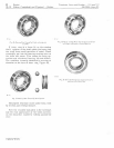
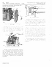
Fi
g.
31-l
nstall
i
ng
Main
Bear
i
ng,n
Bea
ri
ng
Plate
With
bearing
plate
prop
e
rly
supported
,
press
main
bearing,
shielded
side
up.
Fig
'
ure
31.
int.o
bearing
plute
until
hearinR
bottoms
in
bearin~
bore.
Be
Slly
e
sllield
e d
side
is
Il/).
Ball
bcal'lll.f'.s
IliliSt
no/
be
exposed
/0
engine
cYan/,'case
oil.
Litho
in
U.S.1\.


