20
Engine
Tr
acto
rs,
Lawn
a
nd
Garden
- 110
and
112
4
0-4
Camshaft,
Tappets
and
Go
ve
rnor
- T
ec
umseh
S
M-20
59
-(A
pr
-6
7)
REMOVING
GOVERNOR
ROD
INSPE
CT
ING GOV
ERN
OR
GEAR
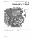
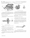
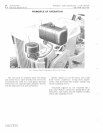
Fig
.
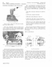
7-Govcrnor
Rod
Loosen
governor
arm
clamp
screw
and
re-
move
governor
lever
assembly.
Remove
paint
from
governor
rod.
Remove
retaining
ring
and
governor
r od
with
lever,
Figure
7.
INSPECTING
CAMSHAFT
Wash
governor
parts
in a
safe
cleaning
solvent
and
wipe
p
ar
ts
dry.
I
~
~
••
,
.,
" J
11111
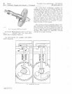
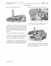
Fig
.
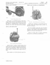
B-Comshof,
Assembly
Check
camshaft
for
cracked,
worn
or
broken
gear
teeth.
Check
operation
of
camshaft
weights,
making
sure
all
parts
are
intact
and
operate
freely.
Check
camshaft
bearings
and
lobes
with
a
micrometer.
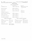
Refer
to
"Spe
c
ifications,"
page
40-7,
for
toler
ance
s.
The
breaker
cam
normally
does
not
show
any
wear
;
therefore,
the
cam
should
never
require
repla
c
ing.
Litho
in
U.S.A.
.'U
""
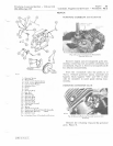
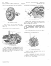
Fig.
9
-Governor
Gear
A " c
mbly
Th
e
over
nor
gear
as
s e
mbly
will
not
nor
ma
lly
show
much
wea
r.
Be
sure
wei
g
hts
ope
rate
fr
ely
and
that
g
ea
rs
aRd
te
e
th
ar
e
in
go
od
con
d
ition.
Heplace
gov
e
rnor
g
ear
assembly
if
necessary.
Check
hol
e
in
clo
se
d e
nd
of
spool,
Fi
gu
re
9.
The
hol
e
is
for
lubri
ca
tion
and
must
be
kept
open
and
clean.
INSPECTING
GOVERNOR
S
HAFT
The
governor
shaft
is
r
ep
laceabl
e.
If
shaft
sho
ws
excessive
w
ea
r
or
damage,
repla
ce
shaft.
Remove
th
e
gov
e
rn
or
s
haft
by
thr
e:l
ding
th
e
sh
aft
with
a
1/4-28
die.
Place
a
spacer
or
num-
ber
of
washers
on
the
shaft
and
turn
on
a
nut.
By
tight
e
ning
the
nut
against
the
was
hers,
the
shaft
will
be
puU-
,
cl
j:
rom
the
cy
linder.
GOVERN8R
Hon
l . .
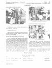
Fig.
TO-Governor
Rod
Assembl
y
Check
lever
on
governor
rod.
Lever
must
be
tight
on
governor
rod
for
best
governor
control
of
engine.
Replace
assembly
if
wear
is
notice-
able.


