40
Electrical
System
Tractors,
Lawn
and
Garden
-
110
and
112
15-2
Charging
System
SM-2059-
(Apr-67)
TESTING
Provided
here
are
instructions
for
testing
electrical
components
on
and
off
the
tractor.
The
purpose
of
the
tests
is
to
isolate
the
cause
of
the
trouble
in
the
generating
system.
A
com-
plete
diagnosis
guide
is
in
Group
5
of
this
section.
Adequate,
approved
electrical
test
equipment
is
required
to
accurately
test
electrical
circuits
and
intelligently
diagnose
unsatisfactory
per-
formance.
Many
servicemen
prefer
to
have
their
elec-
trical
components
tested
by
professionals
using
highly
complex
test
equipment.
Good
automotive
repair
centers
provide
this
service.
The
motor-
generator
and
voltage
regulator
can
be
tested
on
automotive
test
equipment.
The
following
test
procedures
are
recom-
mended
for
dealers
having
their
own
test
equip-
ment.
Equipment
needed
is
listed
at
the
end
of
this
section.
IMPORTANT
:
Because
there
are
many
man-
ufacturers
of
test
equipment,
each
with
their
own
specific
operating
instructions,
it
is
important
to
follow the
manufacturers
recommendations
if
the
procedures
in this
section
should
contradict
those
of
the
manufacturer.
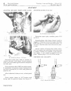
TESTING
CIRCUIT
WIRING
~
P
OO
R
OR
LOOS
E
CO
N
NECT
IONS
~
COR
R
OD
EU
CO
N
NE
CT
IONS
L
WIRES
M 5 87 6
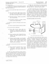
Fig.
3-Foulty
Wiring
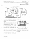
The
wiring
in
the
circuit
is
just
as
important
a
part
of
the
charging
system
as
the
electrical
units
themselves.
Undersize
wire
or
loose
con-
nections
between
the
regula
tor
and
battery
or
poor
ground
connections
between
the
battery
and
generator
will
cause
a
lowering
of
the
charging
rate
to
the
battery.
High
resistance
resulting
from
loose
or
corroded
connections
in
the
charg-
ing
circuit
between
the
generator
and
regulator
will
result
in
a
high
voltage
at
the
generator
and
may
cause
premature
failure
of
the
regulator
pOints.
Litho
in
U.S.A.
A
visual
inspection
will
often
reveal
much
useful
information
relative
to
the
condition
of
the
charging
system.
An
wiring
should
be
vis-
ually
inspected
periodically
for
damaged
insula-
tion.
Faulty
wiring
should
be
replaced.
All
terminals
should
be
checked
for
loose
or
corrod-
ed
connections.
Terminals
should
be
cleaned
and
tightened
if
necessary.
Unwanted
resistance
in
the
circuit
results
in
unwanted
voltage
losses
or
drops.
EXCESSIVE
voltage
drop
in
the
charging
circuit
tends
to
keep
the
battery
in
an
undercharged
condition.
TESTING
MOTOR-GENERATOR
OF
F
TRACTOR
First
check
motor-generator
on
tractor
as
ex-
plained
on
page
10-7
of
Section
40.
Then,
per-
form
the
no-load
test
as
instructed
below
with
the
motor-generator
removed
from
the
tractor.
MOTOR-GENERATOR
NO
LOAD
TEST
V/\R
I
All
Ll
R[SI
S
T~NC
[
VOLT
M
E
TE
~
M 5
76
4
R .
P.
i'l .
I
IiDIC
A
TO
R
AM
ME
TEr{
.,
An
,..----"
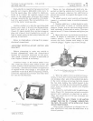
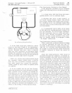
Fig.
4-Checking
Motor·Generotor
Free
Speed
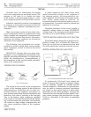
To
perform
the
"No-
Load"
test,
connect
the
motor
in
series
with
a
battery
of
proper
voltage
and
an
ammeter
capable
of
reading
several
hundred
amperes.
A
tachometer
or
rpm
indicator
may
be
used
to
measure
armature
revolutions
per
minute
or
free
speed,
Figure
4.
With
motor
operating
and
the
field
grounded,
measure
the
current
draw
and
note
the
armature
speed.
Com-
pare
these
readings
with
specifications
on
page
15-19
to
determine
if
the
motor
is
operating
properly.


