Power
Train
50
SM
-2059-
(Apr-67)
4-Speed
Transaxle
20-9
T
ractors,
Lawn
and
Garden
-
110
and
112
3.
Washer,
3-cluster
gear
and
spacer
from
shaft
and
pinion
brake.
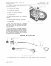
4.
Gear
pinion
and
washer.
5.
Reverse
idler
assembly.
6.
Shifter
rod
and
shaft
assembly.
7.
2-cluster
gear.
8.
Output
shaft
and
washers
(one
at
each
end
of
shaft).
9.
Shaft
and
pinion,
idler
gear
and
washer.
10.
Input
shaft.
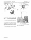
NOTE: Input
shaft,
Figure
18,
is
installed
with
a
press
fit.
Zf
close
inspection
reveals
that
gears
and
bearing
are
satisfactory,
do
not
re-
move
input
shaft.
If
it
is
necessa
ry
to
remove
the
input
shaft,
do
not
use
the
case
itself
to
support
any
of
the
pressure
required
to
separate
the
input
assembly
or
brake
shaft
assembly
from
the
case
halves.
Use
a
large
pipe
to
support
the
pinion
and
press
the
shaft
from
the
opposite
side.
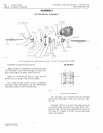
DISASSEMBLING SHIFTER LEVER
..
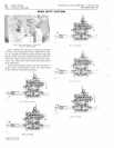
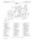
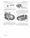
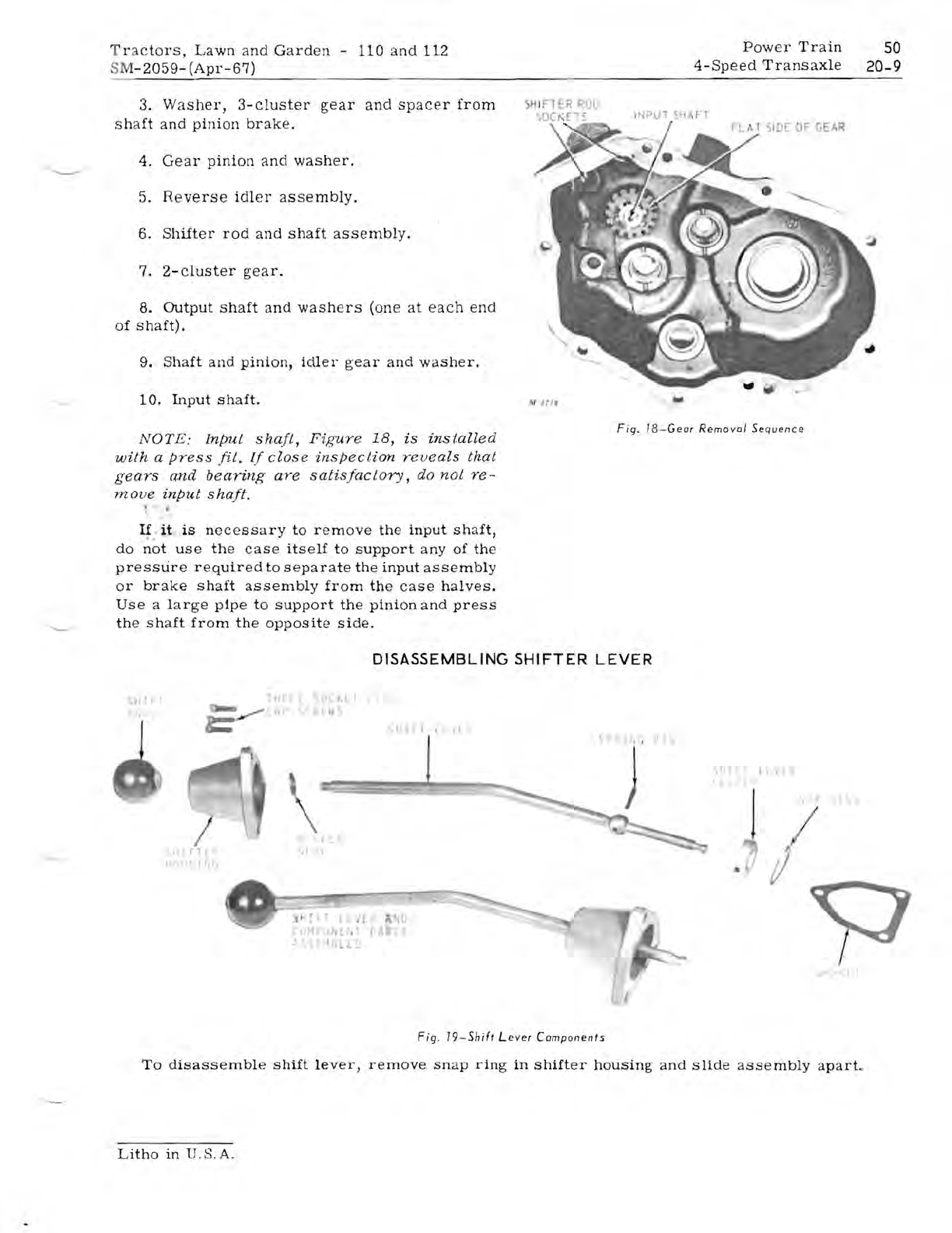
Fig.
18-Geor
Removal
Sequence
.
.
)
.
..
~,r
i l
. ,
I I
til
,J
'I'"
/
! l
"
[r(
. •
, r
l'
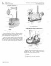
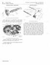
Fig.
19-5hift
Lever
Components
To
disassemble
shift
lever,
remove
snap
ring
in
shifter
housing
and
slide
assembly
apart.
Litho
in
U.S.A.


