60
Hydraulic
System
Tractors,
Lawn
and
Garden
- 110
and
112
15-8
Pump
SM-2059-
(Apr-57)
l '
/
..
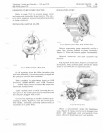
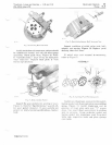
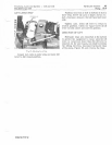
Fig.
21-lnslal/ing
Filler
and
Reservoir
Refer
to
exploded
view,
Figure
3,
and
install
new
filter
gasket
and
filter
to
back
plate
with
two
washers
and
two
machine
screws.
Install
new
O-ring
over
reservoir
mounting
shoulder
and
carefully
slide
reservoir
onto
pump.
Be
sure
port
in
reservoir
is
in
correct
location,
Figure
21.
Secure
reservoir
to
back
plate
with
four
washers
and
machine
screws.
Turn
filler
plug
loosely
into
reservoir
port.
If
valve
assembly
was
removed,
see
page
10-5
for
correct
assembly.
Install
the
assembly
on
the
tractor.
Refer
to
Figure
2,
page
10-1
and
connect
the
hydraulic
hoses
to
the
valve
assembly.
Fill
the
reservoir
with
fluid,
page
5-3.
Adjust
drive
belt
tension
and
relief
valve
pressure
as
explained
on
this
page.
ADJUSTMENTS
DRIVE
BELT
TENSION
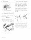
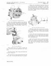
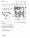
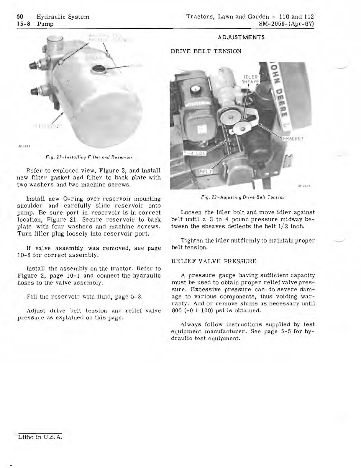
Fig.
22
-Adjusting
Drive
Belt
Tension
Loosen
the
idler
bolt
and
move
idler
against
belt
until
a 3
to
4
pound
pressure
midway
be-
tween
the
sheaves
deflects
the
belt
1/ 2
inch.
Tighten
the
idler
nut
firmly
to
maintain
proper
belt
tension.
RE
LIE
F
VALVE
PRESSURE
A
pressure
gauge
having
sufficient
capacity
must
be
used
to
obtain
proper
relief
valve
pres-
sure.
Excessive
pressure
can
do
severe
dam-
age
to
various
components,
thus
voiding
war-
ranty.
Add
or
remove
shims
as
necessary
until
800
(-0
+ 100)
psi
is
obtained.
Always
follow
instructions
supplied
by
test
equipment
manufacturer.
See
page
5-5
for
hy-
draulic
test
equipment.
Litho
in
U.S.A.


