20
Engine
Tractors,
Lawn
and
Gar
den
-
110
and
112
35-16
SM
-2059-(Apr-67)
Piston,
Crankshaft
and
Flywheel
- T
ecu
mseh
CHECKING
CRANKSHAFT
END
CLEAn
AN
CE
\1
u·
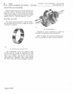
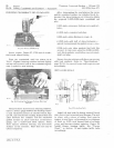
Fig
.
]7
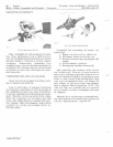
-Scaling
PTO
Bear
ing
Invert
engine,
Figure
37.
PTO
end
of
crank-
shaft
must
extend
freely.
Turn
the
crankshaft
until
the
piston
is
at
T.D.C.
Tighten
bearing
retainer
screws
lightly
and
tap
the
flywhe
el
end
of
the
crankshaft
lightly
with
a
mallet
to
seat
bearing.
Afte r
determining
th
e
ga
p
betw
ee
n
the
cover
and
th
e
machin
ed su
rfa
ce
on
cylinder
bl
o
ck
, de -
termine
the
s
him
thickn
e
ss
as
fo
llo
ws to
obtain
the
required
0.002-0.003-in
ch
c r
anks
haft
e
nd
pl
ay.
0.003-inch-clearanc
e
between
cov
e r
and
cyl
-
ind
er
.
+0.003
-1
nc
h-required
end
play.
0.006-inch-shim
thickness
r
eq
ui} 'c'd.
+
O.003-inch-add
half
of
shim
thickness
.l
.
'-
quired
to
compensate
for
gasket
COrtllJl"l', ;SiOll
0.009-inch-use
shim
gaskets
that
total
this
amount.
In
this
case,
uSingtw
oO
.004
toO
.
005-
inch
thi
ck
gaskets
would
allow
correct
crank-
shaft
end
play.
Secure
h
ar
in
g
retainer
with
three
cap
sc
re
ws
with
lock
washers.
Refer
to
"Specifications,"
page
35-18,
f
or
correct
torque
and
torqu
e
screws
accordingly.
.
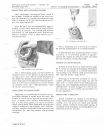
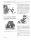
Fig
.
38-CI",cking
Gap
Be/ween
Cylinder
Block
and
Retainer
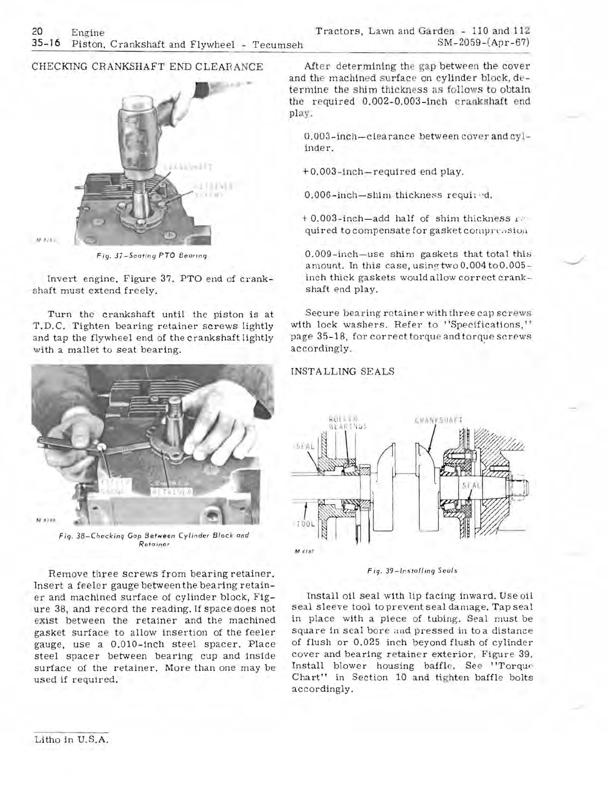
Remove
three
screws
from
bearing
retainer.
Ins
e
rt
a
feeler
gauge
between
the
bearing
retain-
er
and
machined
surface
of
cylinder
block,
Fig-
ure
38,
and
record
the
reading.
If
space
does
not
ex
ist
between
the
retainer
and
the
machined
gasket
surface
to
allow
insertion
of
the
f
ee
ler
gauge,
use
a
0.010-inch
steel
spacer.
Place
steel
spacer
between
bearing
cup
and
inside
surface
of
the
retainer.
More
than
one
may
be
us
ed
if
required.
INST
A
LLlNG
SE
A LS
kl
H I
Lf.:
nL
A.P
t 'I s)
M
618
7
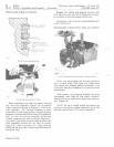
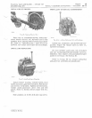
Fig
.
39-l
ns
/alling
S
eals
Install
oil
seal
with
lip
facing
inward.
Use
oil
seal
sleeve
tool
to
prevent
seal
damage.
Tap
seal
in
place
with
a
piece
of
tubing.
Seal
must
be
square
in
seal
bor
e ;illd
pressed
in
to
a
distance
of
flush
or
0.025
inch
beyond
flush
of
cylinder
cover
and
bearing
r e
tain
e r
exterior,
Figure
39.
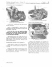
Install
blower
housing
baffl
e.
Se
e
"Torqu
e
Chart"
in
Section
10
and
ti
g
hten
baffl
e
bolts
accordingly.
Litho
in
U.S.A.


