Tractors,
Lawn
and
Garden
-
110
and
112
Electrical
System
40
8M
-2059
-(Apr-57)
Charging
System
15-9
TESTING
CUTOUT
RELAY
CLOSING
VOLT
AGE
. rl/<l i
ll
L[
~I o
l
~
li
'
.i1!.
2
~
0if f'
l-
! " \.) ,\ T T
VOL H
i[TfH
7
O
~'
i
'
rl
XED
PESI
ST
AN
ct
.
M S
ill
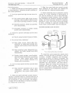
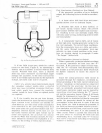
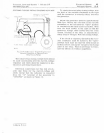
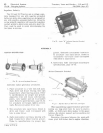
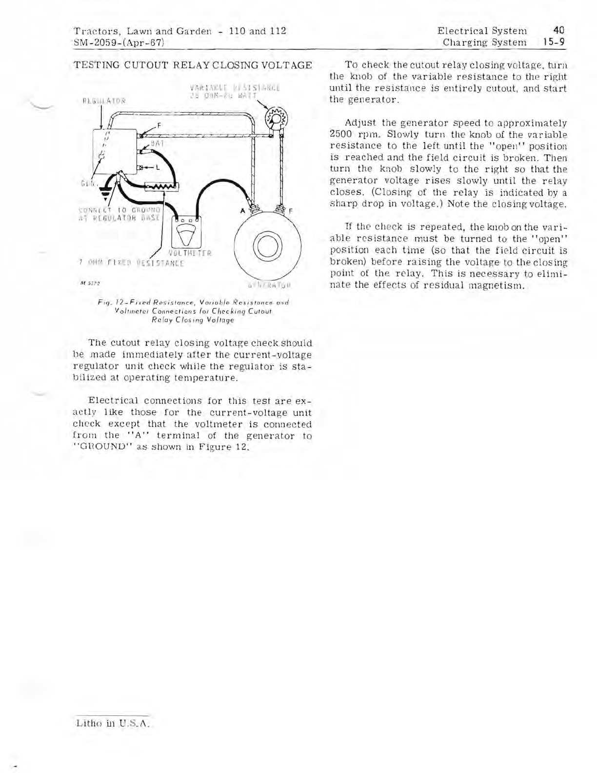
Fig.
12-Fixed
Resistance,
Varioble
Resistonce
ond
Vol/ttlet
er
Connections
for
Checking
Cutout
Relo
y
Closing
Vol/age
The
cutout
relay
closing
voltage
check
should
be
made
imm
ed
iately
after
the
current-voltage
r
egu
lator
unit
check
while
the
regulator
is
sta-
bilized
at
operating
temperature.
Electrical
connections
for
this
test
are
ex-
actly
like
those
for
the
current-voltage
unit
check
except
that
the
voltmeter
is
connected
from
the
"A"
terminal
of
the
generator
to
"GnOUND"
as
shown
in
Figure
12.
To
check
the
cutout
relay
closing
voltage.
turn
the
knob
of
th
e
variable
resistance
to
th
e
ri
ght
until
the
resistance
is
entirely
cutout,
and
start
the
generator.
Ad.iust
the
generator
speed
to
approximately
2500
rpm
.
Slowly
turn
the
knob
of
the
variable
resistance
to
the
left
until
the
" op
en
"
position
is
reached
and
the
field
circuit
is
br
oke
n.
Then
turn
the
knob
slowly
to
the
right
so
that
the
generator
voltage
rises
slowly
until
the
relay
closes.
(Closing
of
the
relay
is
indicated
by
a
sha
rp
drop
in
voltage.)
Note
the
clOSing
voltage.
If
the
check
is
repeated,
the
knob
on
the
vari-
able
resistance
must
be
turned
to
the'
'open"
position
each
time
(so
that
the
field
circuit
is
broken)
before
raiSing
the
voltage
to
the
closing
point
of
th
e
relay.
This
is
nece
ssa
ry
to
elimi-
nat
e
the
effects
of
residual
magnetism.
L
ith
o
i.n
.S.
I\.


