Engine
20
Tractors,
Lawn
and
Garden
-
110
and
112
SM-2059-(Apr-67)
Cylinder
Head
and
Valves
-
Tecums
eh
30-7
HI
GHT
/'rf .'.
,;~;
9
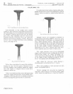
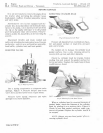
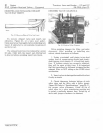
Fig.
18-Yalve
and
Seal
Relationship
Lift
valve
from
seat
eve
ry
eight
or
ten
strokes
to
keep
compound
e
qualized
on
surface
of
valve
seat.
Continue
v
al
ve
lapping
operation
until
a
uniform
lapping
ring
appea
r S
around
enti
re
su
r-
face
of
valve
face.
When
a g
ood
surface
is
attain-
ed,
wash
all
parts
with
s
olvent
to
remove
all
tra
ces
of
lapping
compound.
Dry
parts
thor-
oughly.
Note
position
of
valve
seat
marked
on
valve
face.
Th
e
lappin
g
mark
made
by
the
seat
aft
er
lapping
should
appear
on
or
near
the
center
of
the
va
1
ve
face.
REAMING
VALVE
GUTDES
If
valve
guid
e
clearance
exceeds
maximum
tolerance,
ream
the
guid
e.
When
matching
valves
to
seats,
be
sur
e
valve
seat
is
very
nearly
centered
on
the
valve
face.
The
pOSition
of
the
valve
in
the
seat
is
clearly
evident
a
fter
lapping
th
e
valve,
Figur
e 18.
\ '
ah
'e
Lapping
•
f.(
U
TI I I
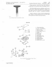
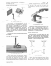
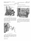
Fig.
19-Lapping
Yo/
ve·s
Coat
fac
e of
valve
sparingly
with
a
fin
g
rade
of
valve
grinding
compound.
Us
e a
vacuu
m
cup
tool,
Figure
19,
to
grip
top
of
valve.
Rotate
valve
in
an
oscillating
circular
motion
on
valve
seat.
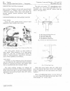
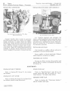
Fig.
20
-
Reoming
Valve
Guides
Use
an
adjustahl
e
ream
el',
Figure
20,
when
en
larging
valve
guides
to
oversize
diamet
e
r.
Se e
"Specification
s
,"
page
30-11
for
valve
guide
oversize
dimensions.
See '
'Special
Tools"
p3
p;
e
30-12,
for
an
adjustable
r e
amer
to
enlar
ge
va
l
ve
g;uides.
CAUTION:
Do
not
enlarge
lifter
guides,
be-
cause
lifters
with
oversize
stems
are
notavall-
able.
Litho
in
U.S.A.


