50
Power
Train
Tractors,
Lawn
and
Ga
rden
-
110
and
112
20-16
4-Speed
Transaxle
SM-
2059-
(Apr-
6 7)
PINIO
GEAR
EEOLE SF fiRING
AND
SIII'PORT
\f
J/U
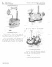
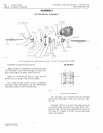
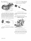
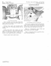
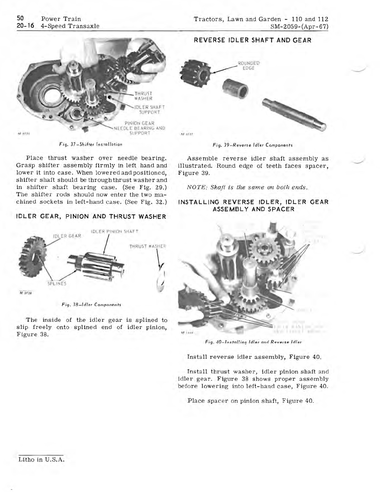
Fig.
37-Shifter
In
s
tallation
Place
thrust
washer
over
needle
bearing.
Grasp
shifter
assembly
firmly
in
left
hand
and
lower
it
into
case.
When
lowered
and
position
ed,
shifter
shaft
should
be
throu
gh
thrust
washer
and
in
shifter
shaft
bearing
case.
(See
Fig.
29.)
The
shifter
rods
should
now
enter
the
two
ma-
chined
sockets
in
left-hand
case
.
(See
Fig.
32.)
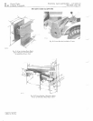
IDLER
GEAR, PINION
AND
THRUST
WASHER
IDLER
PI
11011
SHAFT
THRUST
ASH
E~:
I
~
I
I
ItrJl1'
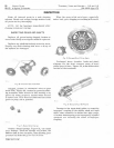
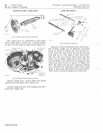
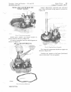
Fig.
38-ldl"r
Components
The
inside
of
the
idler
gear
is
splined
to
slip
freely
onto
splined
end
of
idler
pinion,
Figure
38.
REVERSE
IDLER
SHAFT
AND
GEAR
ROUNDED
EDGE
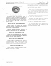
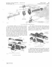
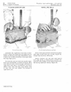
Fig.
39-Revcrse
Idle
r
Components
Assemble
reverse
idler
shaft
assembly
as
illustra
ted.
Round
edge
of
teeth
faces
spacer,
Figure
39.
NOTE:
Shaft
is
the
same
on
both
ends.
INSTALLING REVERSE IDLER, IDLER
GEAR
ASSEMBLY
AND
SPACER
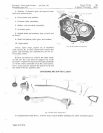
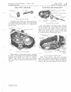
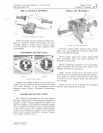
Fig.
40-lllstolling
Idler
and
Reverse
Idler
Install
reverse
idler
assembly,
Figure
40.
Install
thrust
washer,
idler
pinion
shaft
and
idler
gear.
Figure
38
shows
proper
assembly
before
lowering
into
left-hand
case,
Figure
40.
Place
spa
ce
r on
pinion
shaft,
Figure
40.
Litho
in
U.S.A.


