Tractors,
Lawn
and
Garden
-
110
and
112
SM-2059-
(Apr-67)
"
'.
lJ
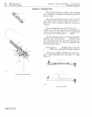
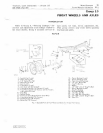
Fig
.
17-Connecting
Drag
Link
to
Lever
Arm
Miscellaneous
70
Steering
Linkage
5-9
Connect
drag
link
to
lever
arm,
Figure
17
and
tighten
nut
firmly.
NOTE
:
It
is
important
that
drag
link
is
posi-
tioned
with
bend
facing
the
center
of
the
tractor
before
tightening
nuts.
Refer
to
Figure
8,
page
5-6
and
install
steer-
ing
wheel.
Refer
to
"Specifications,"
page
5-11
for
steering
wheel
retaining
nut
to
rque.
Insert
O-ring
into
slot
in
steering
whe
el
cap
and
press
cap
into
steering
wheel.
Adjust
the
steering
gear
mechanism
a
ccord-
ing
to
the
sequence
e
xplained
below.
ADJUSTMENTS
STEERING
GEAR
Adjust
steering
mechanism
in
the
sequence
described
below:
Make
these
adjustments
when
excessive
play
(loose
steering)
is
noticed
or
if
steering
becomes
difficult.
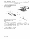
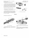
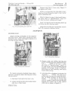
Fig.
18-Steering
Gear
Adjustment
To
remove
excessive
backlash
(loose
steer-
ing)
and
to
properly
adjust
steering
gear,
follow
this
procedure:
1.
Disconnect
ball
joint
from
lever
arm.
2.
Loosen
jam
nut
and
turn
stud
counterclock-
wise
two
or
three
turns.
Litho
in
U.S.A.
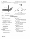
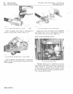
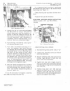
Fig.
19-5teering
Gear
Adiustment
3.
Remove
cotter
pin
holding
adjusting
plug
in
gear
housing.
Steering
columns
on
Trac-
tors
(
-51052)
do
not
have
a
cotter
pin.
Refer
to
"SpeCifications,"
page
5-11,
for
plug
torque
a
nd
turn
adjusting
plug
into
housing
until
proper
torque
is
obtained.
Back
plug
out
until
steering
wheel
turns
freely
with
no
drag.
4.
Lock
plug
after
adjustment
is
obtained.
On
Tractors
(
-51052),
lock
plug
by
up-
setting
plug
threads
with
a
punch
and
ham-
mer
as
Shown
in
Figure
13. On
Tractors
(51053-
),
lock
plug
by
turning
plug
only
far
enough
to
insert
cotter
pin
through
housing
and
closest
slot
in
plug.
Spread
cotter
pin as shown in
Figure
14.


