20
Engine
15-16
Piston,
Crankshaft
and
Flywheel
-
Kohler
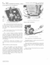
ATTACHING
ROD
TO
CRANKSHAFT
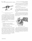
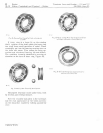
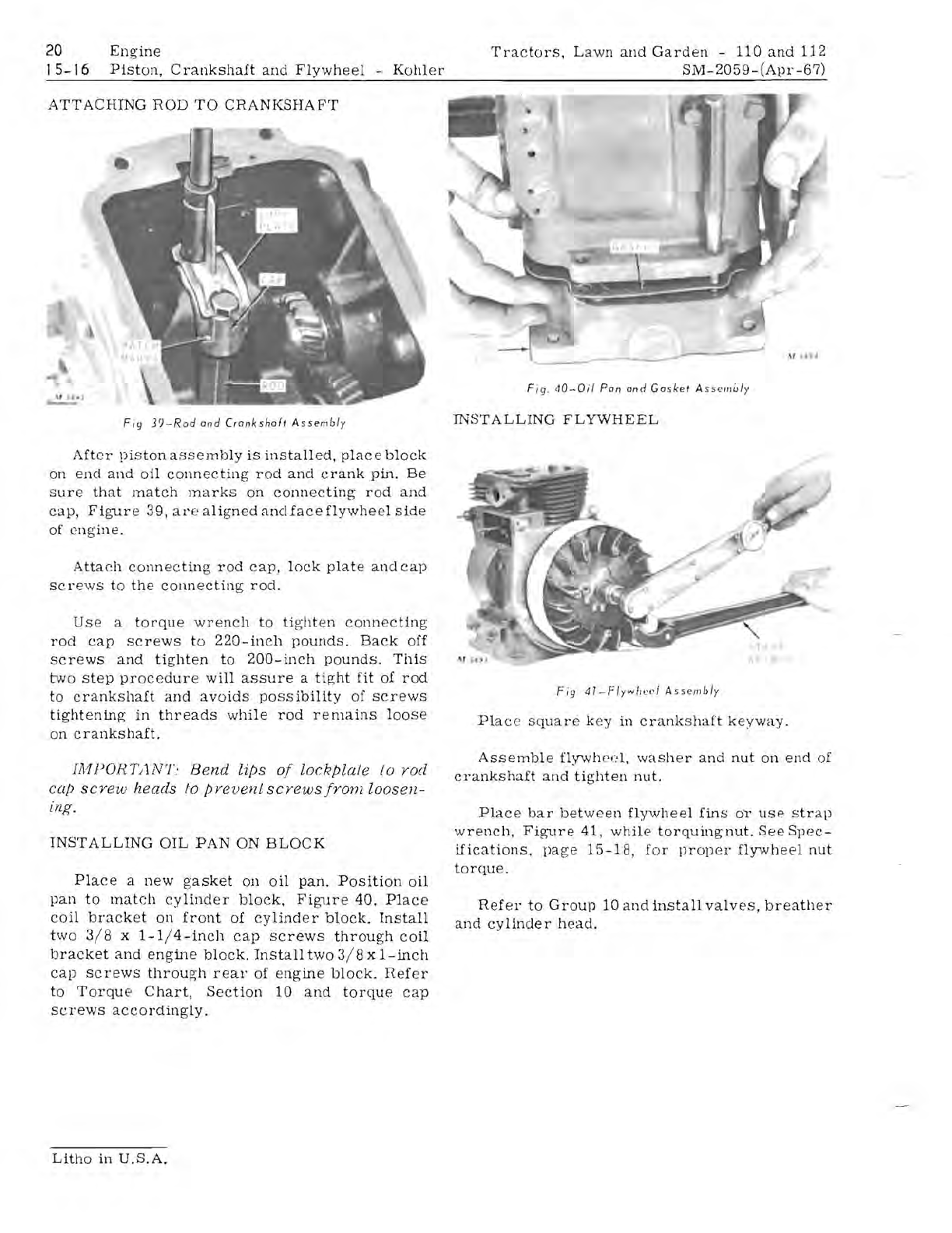
Fig
3?-Rod
and
Crankshaft
Assembl
y
After
piston
assembly
is
installed,
place
block
on
end
and
oil
connecting
rod
and
crank
pin.
Be
Sure
that
match
marks
on
connecting
rod
and
cap,
Figure
39
,
al'e
aligned
anclface
flywhe
el
side
of
eng
ine
.
Attach
connecting
rod
cap,
lock
plate
and
cap
scr
ews
to
the
connecting
rod.
Use
a
torque
wrench
to
tighten
connecting
rod
cap
screws
to
220-inch
pounds.
Back
off
screws
and
tighten
to
200-inch
pounds.
This
two
step
procedure
will
assure
a
tight
fit
of
rod
to
crankshaft
and
avoids
possibility
of
screws
tightening
in
threads
while
rod
remains
loose
on
crankshaft.
IA1PORT/lNT'
Bend
lips
of
lockpla/e
/0
yod
cap
scyew
heads
to
pvevenLscyewsfronz
loosen-
ing.
INSTALLING
OIL
PAN
ON
BLOCK
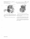
Place
a
new
g'asket
Oll
oil
pan.
Position
oil
pan
to
match
cylinder
block.
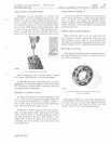
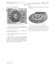
Figure
40.
Place
coil
bracket
on
front
of
cylinder
block.
Install
two
3/8
x
1-1/4-incl1
cap
Screws
through
coil
bracket
and
engine
block.
Install
two
3/8
x
I-inch
cap
screws
through
rear
of
engine
block.
Hefer
to
Torque
Chart,
Section
10
and
torque
cap
screws
accordingly.
Tractors,
Lawn
and
Garden
-
110
and
112
SM-2059-(Apr
-67)
F
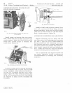
ig.
40-0il
Pan
an d
Ga
sket
A
ssc'mu/y
INSTALLING
FLYWHEEL
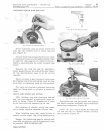
Fig
41-Flywlll'cI
A
ssemb
ly
Plac
e
square
k
ey
in
crankshaft
keyway.
Assemble
flywh
cf.'
l.
washer
and
nut
on
end
of
crankshaft
and
tighten
nut.
Place
bar
between
flywheel
fins
01'
use
strap
wrench,
Fig'ure
41,
while
torquing'nut.
See
Spec-
ifications,
page
15
-18,
for
prop
er
flywheel
nut
torque.
Refer
to
Group
10
and
install
valv
es,
breather
and
cylinder
head.
Litho
in
U,S.A.


