i
20
Engine
Tractors.
Lawn
anri
Garden
-
110
and
112
20-4
Camshaft.
Tappets
and
Gov
rn
o
r-Kohler
SM
-2059
-(Apr
-67)
R EMOVTNG
GOVERNOR
Loosen
nut
on
g
ov
rnor
arm
h
aft
and
slide
off
::
tlJ
e
xt
e
rnal
part
s.
\'
O
T1:,
;"
Do
1101
at!
III/JI
10 r a
mO
I e
p:
Ol
e r
llor
C
ros
s
sh
af
t
(rorn
ouLs
id
e
of
eng i
ne.
[t
nm
s I
be
r
ei
I/o/
cd
(rom
lite
insi
de .
Turn
bl
ock
upside
duw
l1
and
r m ov go
ve
rnor
s t
op
pin
(23.
Fi
g.
5)
ane! c op
per
was
i1
c l'.
Go
v-
ernor
a
ss
embly
and
cr
o s
shaft
(2, Fi . 5) may
no
w be
l·
e
moved.
P E
CT
ING
CA
MSHAFT
W
as
h
gov
e
rnor
and
a
msh
a
ft
in
sa
fe c l a
ning
solve
nt
and
wip
e
pa
rts
dry.
Check
ca
ms ha ft
for
Cl"
ck
ct,
w
orn
o r
brok
en
gp
a r t
eet
h.
Ch
ec
k
op
e
ration
of
ACH ('., m s ha
ft
a
nd
we
ig
hts
nu
ki
ng
sure
J
ll
pa
rt
s a
re
inta
et
a
nd
ope r a
te
fr
ee
ly.
S OT
l
~
··
I Ien C
I/
iii
S /ta
ft
s
(IJ'
e
([/
,(
lilah
le f
or
se)'-
r'i
ce
on ly (Is
({
('(
mlplete
ass
em
hly
exc
epl
f a
!"
the
,fly
r eix
hl
sp
rin
g . ln
dil'ir/ual
parts
ave
(l(,(lil
ab le
/0)'
s/)(ly1,
ad
r
ali
ce
cwus/w
f
ts.
SP
ECTlNG
GOVERNOR
GEAR
\l
III
J
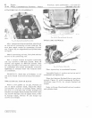
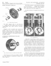
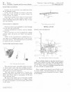
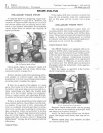
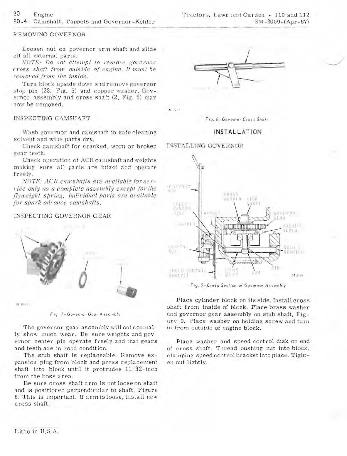
Fig
7-Govcrnor
Gear
As
s
embly
The
governor
gear
assembly
will
not
normal-
ly
show
much
wear.
Be
sure
weights
and
gov-
e
rnor
center
pin
operate
freely
and
that
gea
rs
and
teeth
are
in
f2
;
ood
condition.
The
stub
shaft
is
replaceable.
Remove
e
x-
pansion
plug
from
block
a
nd
P]'(
?
SS
replac
e
ment
shaft
into
block
until
it
protrud
es
1l
,'
32
-inch
from
the
boss
area.
Be
sure
crass
shaft
arm
is
not
loose
on
shaft
and
is
positioned
perpendicul
ar
to
shaft,
Fi
g
ure
8.
This
is
illlportant.
If
arm
is
loose.
install
new
cr
O
Ss
shaft.
Lith
o
in
U.S.A.
.~I
c
~
!
I
I
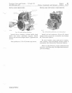
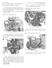
Fi
q, 8-
Gov
"
rno
r Cr o
ss
S
;'ol,
INST
ALL
AT ION
T
ST
AL
LIN
G
GOV
E R
NOR
.
~
,.
f
',
'
i l
I
...
1\
t
LI.
S,
L 1 ;
'" T
',PLio '/
Ll.fIi.
'
l1
,H
SiY,
~
..
. ! "
L,)::F
,ln
' . t UI r
hE
~I<
I
'1\.
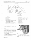
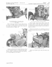
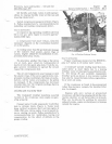
Fi9.
9- C
ross·SC'
ct
Jon
of
Goye r
no
r A
sscm
bly
Pla
c e
cylind
e r
block
on
its
s
ide.
Ins
ta
ll
cro
s
shaft
fr
om
inside
of
bl
o
ck.
Place
br
a
ss
wash
e r
and
governor
ge
ar
as
s e
mbl
on
s
tub
sh
aft,
Fi
g-
ure
9.
Place
washer
on
holding
screw
and
tu
rn
in
from
outside
of
en
gine
block.
Place
washer
and
speed
control
disk
on
end
of
cross
shaft.
Thr
ead
bushing
nut
into
bl
o
ck,
clamping
speed
cont
r ol b
racket
into
plac
. T ig
ht-
en
nut
lightly.


