40
Electrical
System
Tractors,
Lawn
and
Garden
- 110
and
112
15-8
Charging
System
SM-2059-(Apr-67)
TESTING
REGULATOR
The
electrical
settings
of
the
cutout
relay
a.nd
the
current-voltage
regulator
unit
may
be
checked
either
on
or
off
the
tractor
without
re-
moving
the
regulator
cover.
When
bench
checks
are
made,
the
regulator
must
be
connected
only
to a
generator
of
the
type
for
which
it
is
designed.
Results
obtained
with
any
other
type
of
generator
will
be
meaningless.
When
the
regulator
is
checked
on a
tractor,
all
loads
(including
igni-
tion)
connected
to
the
"L"
terminal
must
be
switched
off.
To
furnish
ignition
current
during
tests
for
electrical
settings
,
use
a
jumper
lead
to
connect
free
end
of
battery
lead
direct
to
primary
terminal
of
ignition
coil
(switch
side).
TESTING
CURRENT-VOLTAGE
REGULATOR
UNIT
SETTING
REG
UL
AT
OR
VARIArJ
LE
RE
S ISTAl,
cr
ZS O
Hf1
- 2
::l
l
{ITT
7
~HM
Fr
X
E~
~[
S
r
S
rAN
C E
GE
'
1(
::"
, T
OP.
,ow
S7/~
1
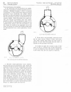
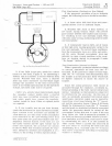
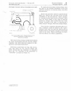
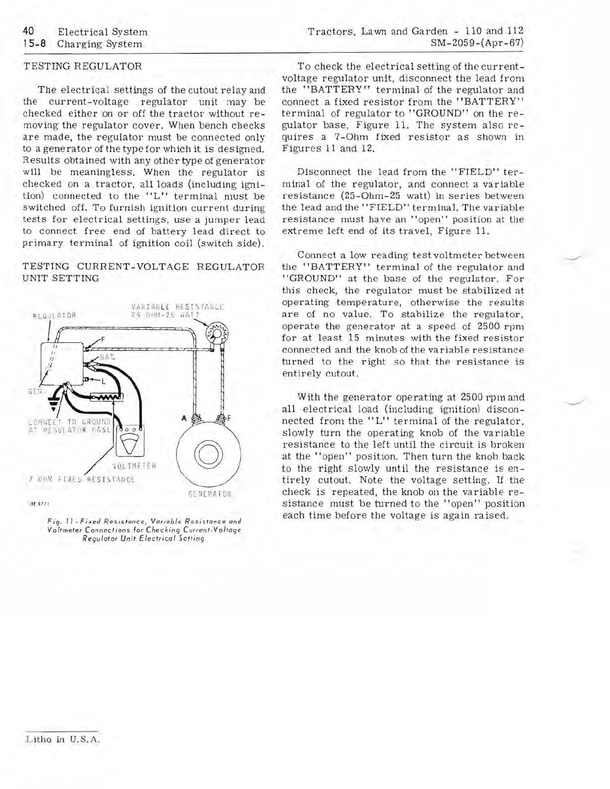
Fig
,
II-Fixed
ReSistance
,
Variable
Resistance
and
Voltmeter
Connections
for
Checking
Curr
ent
.Voltage
Regulator
Unit
Electrical
Setting
To
check
the
electrical
setting
of
the
current-
voltage
regulator
unit
,
disconnect
the
lead
from
the
"BATTERY"
terminal
of
the
regulator
and
connect
a
fixed
resistor
from
the
"BATTERY"
terminal
of
regulator
to
"GROUND"
on
the
re-
gulator
base,
Figure
11.
The
system
also
re-
quires
a
7-0hm
fixed
resistor
as
shown
in
Figures
11
and
12.
Disconnect
the
lead
from
the"
FIELD"
ter-
minal
of
the
regulator,
and
connect
a
variable
resistance
(25-0hm-25
watt)
in
series
between
the
lead
and
the'
'FIELD"
terminal.
The
variable
resistance
must
have
an
"open"
pOSition
at
the
extreme
left
end
of
its
travel,
Figure
11.
Connect
a low
reading
test
voltmeter
between
the
"BATTERY"
terminal
of
the
regulator
and
"GROUND"
at
the
base
of
the
regulator.
For
this
check,
the
regulator
must
be
stabilized
at
operating
temperature,
otherwise
the
results
are
of
no
value.
To
stabilize
the
regulator,
operate
the
generator
at
a
speed
of
2500
rpm
for
at
least
15
minutes
with
the
fixed
resistor
connected
and
the
knob
of
the
variable
resistance
turned
to
the
right
so
that
the
resistance
is
entirely
cutout.
With
the
generator
operating
at
2500
rpm
a.nd
all
electrical
load
(including
ignition)
discon-
nected
from
the
"L"
terminal
of
the
regulator
,
slowly
turn
the
operating
knob
of
the
variable
resistance
to
the
left
until
the
circuit
is
broken
at
the
"open"
pOSition.
Then
turn
the
knob
back
to
the
right
slowly
until
the
resistance
is
en-
tirely
cutout.
Note
the
voltage
setting.
If
the
check
is
repeated,
the
knob
on
the
variable
re-
sistance
must
be
turned
to
the
"open"
pOSition
each
time
before
the
voltage
is
again
raised.
Lit
ho
in U.S.A.


