Tractors,
Lawn
and
Garden
-
110
and
112
Power
Train
50
SM-
2059-
(Apr-67)
4-Speed
Transaxle
20-15
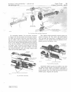
Fig
.
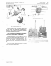
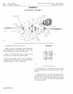
34-Shifter
Shaft
and
Gear
Components
M
J1:1
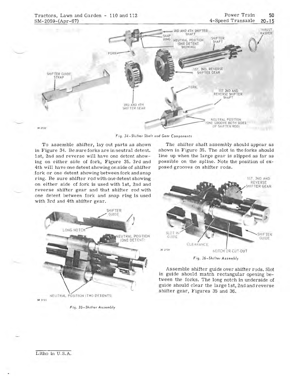
To
assemble
shifter,
layout
parts
as
shown
in
Figure
34.
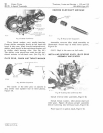
Be
sure
forks
are
in
neutral
detent.
1st,
2nd
and
reverse
will
have
one
detent
show-
ing
on
either
side
of
fork,
Figure
35.
3rd
and
4th
will
have
one
detent
showing
on
side
of
shifter
fork
or
one
detent
showing
between
fork
and
snap
ring.
Be
sure
shifter
rod
with
one
detent
showing
on
either
side
of
fork
is
used
with
1st,
2nd
and
reverse
shifter
gear
and
that
shifter
J,"od
with
one
detent
between
fork
and
snap
ring
is
used
with
3rd
and
4th
shifter
gear.
~lEUTRAL
PO~IT
!
ON
IT
WO
DE
l E
TS
,
M
J1lJ
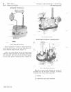
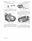
Fig.
35-Shifler
Ass.,mbly
Litho
in
U.S.A.
THRUST
W
HER
_
lRD
AND
HH
SHIFTER
511A1I
t
EUTRAl
POSITION
lONE
DETENT
/
SHO
INC)
IS1
, P
AND
REVERSE
SHIFTER
SHAFT
,/
Il
EUTR
AL
POSITIO
to
~r
GROovE
BOTH
SIDES
OF
~HIFTE.R
ROD)
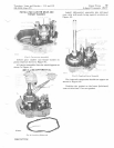
The
shifter
shaft
assembly
should
ap
pe
ar
as
shown
in
Figure
35.
The
slot
in
the
forks
should
line
up
when
the
large
gear
is
slipped
as
far
as
possible
on
the
spline.
Note
the
position
of
ex-
posed
grooves
on
shifter
rods.
1
ST
2ND
NO
REV
ERSE
SH
I
FTER
GEAR
CLEAR"NCE
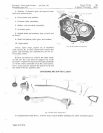
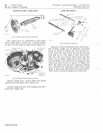
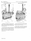
Fig_
36-Shifter
Assembly
Assemble
shifter
guide
over
shifter
rods.
Slot
in
guide
should
match
rectangular
opening
be-
tween
the
forks.
The
long
notch
in
underside
of
guide
should
clear
the
large
1
st,
2nd
and
reverse
shifter
gear,
Figures
35
and
36.


