Tractors,
Lawn
and
Gard
en
-
110
an
cl
112
Electrical
3yst
ill
40
SM-
2059-
(Apr-
67)
Chargin
g
Syst
e m
15- 1
Group
15
C
HAR
GI NG
SYSTEM
GENERAL
IN
FO
RMA
TION
,
J'
r
llil
Y
i't!
A
'(
PFilU
llDi,
TO
L ' lolll
,
llll
t:
1)
[ "
-
~
----------------------
----..
.-----'
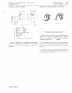
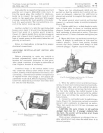
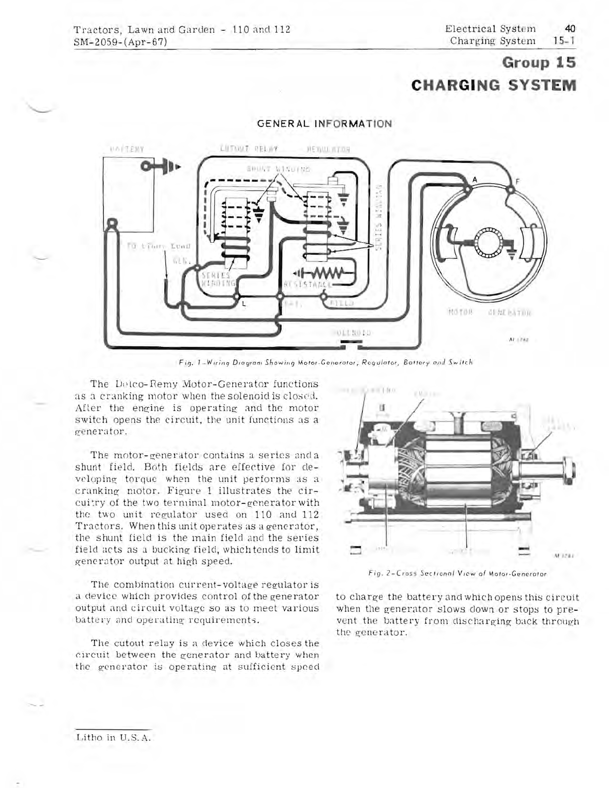
Fig,
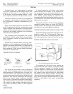
I-Wiring
O"'
9ram
Showin']
Motor
.
Gellerator,
Regulator
,
BatlN
y
and
Switch
The
U'
~
lco-nemy
iv
l
otor
-Genel'at
or
fun
c
tions
as
a c
ranking
m otor
when
the
solenoid
is
closec\.
AIl
e
I'
the
engine
is
operatin
g
Clnd
the
mot
or
s
witch
opens
the
circuit,
the
unit
functi
o
ns
as
a
~L'
nera
to
r,
The
motor-g
e
nel'at
or
contains
a
s(~ries
ancl a
shunt
fi e
ld.
B
oth
fields
,He
effective
[or
de-
ve
l
opin
g to
rque
when
the
unit
perfonns
:JS
a
e rankin!:!: m
oto
r.
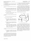
Figure
1
illustrates
the
c
ir-
c
ui~ry
of
the
two
terminal
l11otor-generatorwith
the
two
unit
regulator
used
on
110
and
112
Tractors.
When
this
lmitoperates
as
a
generator,
th
e s
hunt
field
is
the
main
fielcl
and
the
series
field
acts
as
a
bucking
fi e
ld,
which
te
nds
to
limit
f',"Cner,1tor
output
"t
hig
'h
speed.
Th
e
co
mbin3tion
cu
rrent-voltag
e
regulatol'
is
a
cievice
which
provicles
control
of
the
generator
output
and
circuit
voltage
so
as
to
meet
various
batt
c
l'Y
;mc\
operating
l'
cqu
ir
e mcnt.:;.
The
cutout
rela
y
is
a de
vice
w
hich
clos
es
the
c
ir
c
uit
between
the
gener3tor
and
battery
when
the
generator
is
operating
at
suffici
ent
speec\
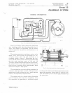
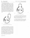
Fi
g.
2
-Cr
o55
S
ectlonol
V,ew
01 Mot
ol·
Generator
to
charge
the
battery
and
which
opens
this
circuit
when
the
g'
ener,ltor
slows
clown
or
stops
to
pre-
vent
th
e
battel'Y
fr
om
cliseharg'ing
back
throll
gh
th
e
ge
ne
rator,
Litho
in
U.S.
A.


