125
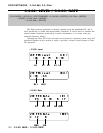
VOICE EDIT MODE / 3: Full Edit. 3-3: Filter
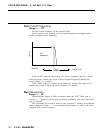
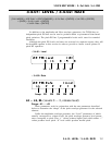
3-3-02: LEVEL / 3-3-03: RATE
L0 … L4, RL1, RL2 (Levels 0 … 4, release levels 1 & 2)
Range: -63 ... +63
The level parameters work in conjunction with the rate parameters described
below to determine the “shape” of the cutoff envelope generator for the se-
lected filter. This function is only available if the “Ctrl” parameter (page 123)
is set to “EG.”
The cutoff envelope generator level parameters correspond to cutoff fre-
quency. Plus “+” values produce higher cutoff frequencies while minus “–”
values produce lower cutoff frequencies. “0” level values produce the normal
cutoff frequency as determined by the cutoff parameter (See “Cof” on page
122).
R1 … R4, RR1, RR2 (Rates 1 … 4, release rates 1 & 2)
Range: 0 ... +63
These parameters work in conjunction with the level parameters described
above to determine the “shape” of the cutoff envelope generator for the selected
filter. This function is only available if the “Ctrl” parameter (page 123) is set
to “EG.”
The “Rate” parameters work in the same way as the amplitude and pitch
envelope generator rate parameters: a setting of “63” produces the fastest (al-
most instantaneous) rate between levels, while the minimum setting of “0”
produces the slowest change.
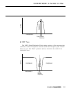
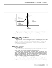
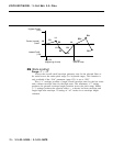
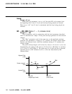
The filter envelope begins at L0 (Level 0), moves to L1 (Level 1) at a rate
determined by the setting of R1, then to L2 (Level 2) at R2 (Rate 2), then to
L3 (Level 3) at R3 (Rate 3), and then to L4 (Level 4) at R4 (Rate 4). The
cutoff stays at L4 until the key is released, and then moves to RL1 (Release
Level 1) at the rate determined by RR1 (Release Rate 1), and finally to RL2
(Release Level 2) at RR2 (Release Rate 2).


