


94
S:\agilent\8920\8920b\PRGGUIDE\BOOK\CHAPTERS\ch3intro.fb
Chapter 4, GPIB Commands
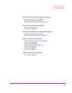
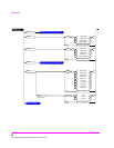
GPIB Syntax Diagrams
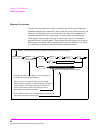
Diagram Conventions
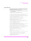
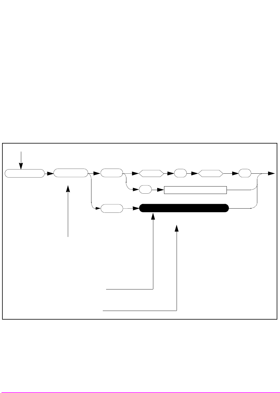
Use the following diagram to see the conventions used in the syntax diagrams.
Statement elements are connected by lines. Each line can be followed in only one
direction, as indicated by the arrow at the end of the line. Any combination of
statement elements that can be generated by starting at the root element and
following the line the proper direction is syntactically correct. An element is
optional if there is a path around it. The drawings show the proper use of spaces.
Where spaces are required they are indicated by a hexagon with the word “space”
in it, otherwise no spaces are allowed between statement elements.
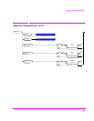
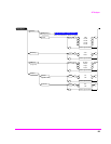
string
Returns quoted string
(Field Name)
(*Does not included the :STATe command)
:CDCSs
:CODE
space
:RATE
See Real Number Setting Syntax*
‘ ‘
?
AFGenerator2
Root Element
Indicates the name of the display screen’s field that is
controlled by this command element.
Directs the user to a specific Instrument Command,
Measurement Command, or Number Setting Command
syntax diagram. The Number Setting Commands are
used to format numeric data and configure various
instrument measurement parameters.
Notes indicate which, if any, Number Setting Commands are
not supported by this particular path.
(Black oval at root level indicates continuation from previous page.)