45
Chapter 1, Using GPIB
Getting Started
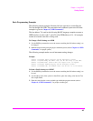
Basic Programming Examples
The following simple examples illustrate the basic approach to controlling the
Test Set through the GPIB. The punctuation and command syntax used for these
examples is given in
Chapter 4, “GPIB Commands.”.
The bus address 714 used in the following BASIC language examples assumes a
GPIB interface at select code 7, and a Test Set GPIB address of 14. All examples
assume an external controller is being used.
To Change a Field’s Setting over GPIB
1. Use the DISPlay command to access the screen containing the field whose setting is to
be changed.
2. Make the desired setting using the proper command syntax (refer to Chapter 4, “GPIB
Commands,” for proper syntax).
The following example makes several instrument setting changes:
Example
OUTPUT 714;"DISP RFG" !Display the RF Generator screen.
OUTPUT 714;"RFG:FREQ 850 MHZ" !Set the RF Gen Freq to 850 MHz.
OUTPUT 714;"RFG:OUTP ’DUPL’"!Set the Output Port to Duplex.
OUTPUT 714;"DISP AFAN"!Display the AF Analyzer screen.
OUTPUT 714;"AFAN:INP ’FM DEMOD’"!Set the AF Anl In to FM Demod.
To Read a Field’s Setting over GPIB37
1. Use the DISPlay command to access the screen containing the field whose setting is to
be read.
2. Use the Query form of the syntax for that field to place the setting value into the Test
Set’s output buffer.
3. Enter the value into the correct variable type within the program context (refer to
Chapter 4, “GPIB Commands,”, for proper variable type).


