


378
S:\agilent\8920\8920b\PRGGUIDE\BOOK\CHAPTERS\ibasic.fb
Chapter 7, IBASIC Controller
Method #1. Program Development on an External BASIC Language Computer
Program Development Procedure
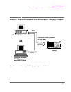
As discussed in “Overview of the Test Set” on page 26, the Test Set has two
GPIB buses, an internal GPIB at select code 8 and an external GPIB at select code
7. The Test Set’s built-in IBASIC controller uses the internal GPIB to
communicate with the Test Set’s various instruments and devices. The process of
developing a program on an external BASIC language computer utilizes this
hardware feature to an advantage. First, develop the program directly on the
external BASIC language computer treating the Test Set as a device on the
external BASIC language computer’s GPIB. For example, to setup the Test Set’s
RF Generator use the OUTPUT command with the Test Set’s GPIB address. If the
select code of the GPIB card in the external BASIC language computer is 7 and
the address of the Test Set is 14 the address following the OUTPUT command
would be 714. When the command executes on the external BASIC language
computer the information on how the Test Set’s RF Generator is to be configured
is sent to the Test Set through its external GPIB bus. After the program is fully
developed, making it run on the Test Set is simply a matter of changing the
address of all the GPIB commands to 8XX (Test Set internal GPIB bus) and
downloading the program into the Test Set’s IBASIC controller and executing it.
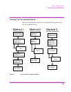
There are two ways of allowing easy conversion of all GPIB commands to a different
address. The first way is to establish a variable to which the 3-digit address number is
assigned.
For example
10 Addr = 714 ! Sets the value of variable Addr to be 714.
20 OUTPUT Addr;"*RST"!Commands the Test Set to reset at address 714.
To change the address, simply change the value of variable Addr to 814.
For example
10 Addr = 814 ! Sets the value of variable Addr to be 814.
20 OUTPUT Addr;"*RST"! Commands the Test Set to reset at address 814.
A second method is to assign an I/O path to the desired I/O port.
For example
To control device #14 on the port with select code 7.
20 ! Establishes IO path to select code 7 address 14
10 ASSIGN @Device TO 714
30 ! Commands Test Set to reset at address 714.
20 OUTPUT @Device;"*RST"
To change the address, simply change line 10 to
10 ASSIGN @Device TO 800.