


360
S:\agilent\8920\8920b\PRGGUIDE\BOOK\CHAPTERS\ibasic.fb
Chapter 7, IBASIC Controller
Interfacing to the IBASIC Controller using Serial Ports
Interfacing to the IBASIC Controller using Serial Ports
This section describes how to interconnect the Test Set to an external PC or
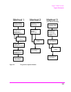
terminal using the Test Set’s serial I/O ports. Program development methods #2
and #3 use PC’s or terminals connected to the Test Set through the Test Set’s serial
I/O ports. To determine which programming environment best fits your
application, refer to
“Choosing Your Development Method” on page 373.
Test Set Serial Port Configuration
To prepare for IBASIC program development, the Test Set must first be
configured to operate with a PC or terminal.
This includes,
• Hardware
•Cables
• Screens - I/O CONFIGURE and TESTS (IBASIC Controller)
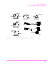
There are two independently controllable serial interfaces in the Test Set, each
using a 3-wire transmit / receive / ground implementation of the RS232 standard.
The IBASIC Controller can send and receive data from either port by using its
assigned select code.
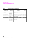
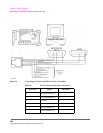
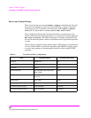
Serial Port Information
The Test Set’s rear-panel RJ-11 connector has 6 conductors. (Note that this jack
appears the same as a common 4-conductor RJ-11 telephone jack, but the Test Set
jack uses 6 conductors). Three of the wires are designated as Serial I/O Port
address 9, and the other three wires are designated Serial I/O Port address 10 (also
referred to as Serial Port B). These select codes cannot be changed.