


247
Chapter 5, Advanced Operations
Status Reporting
Status Register Model
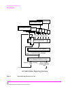
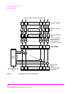
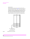
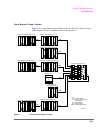
This section explains how the status registers are structured in the Test Set. The
generalized status register model shown in
Figure 5 on page 246 is the basis upon
which all the status registers in the Test Set are built. The model consists of a
Condition Register, Transition Filters, an Event Register, an Enable Register, and
a Summary Message. A set of these registers is called a Status Register Group.
Condition Register. A condition is a Test Set state that is either TRUE or FALSE
(an GPIB command error has occurred or an GPIB command error has not
occurred). Each bit in a Condition Register is assigned to a particular Test Set
state. A Condition Register continuously monitors the hardware and firmware
states assigned to it. There is no latching or buffering of any bits in a Condition
Register; it is updated in real time. Condition Registers are read-only. Condition
Registers in the Test Set are 16 bits long and may contain unused bits. All unused
bits return a zero value when read.
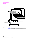
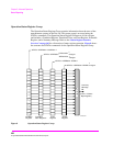
Transition Filters. For each bit in the Condition Register, the Transition Filters
determine which of two bit-state transitions will set the corresponding bit in the
Event Register. Transition Filters may be set to pass positive transitions (PTR),
negative transitions (NTR) or either (PTR or NTR). A positive transition means a
condition bit changed from 0 to 1. A negative transition means a condition bit
changed from 1 to 0.
In the Test Set, the Transition Filters are implemented as two registers: a 16-bit
positive transition (PTR) register and a 16-bit negative transition (NTR) register.
A positive transition of a bit in the Condition register will be latched in the Event
Register if the corresponding bit in the positive transition filter is set to 1. A
positive transition of a bit in the Condition register will not be latched in the Event
Register if the corresponding bit in the positive transition filter is set to 0. A
negative transition of a bit in the Condition register will be latched in the Event
Register if the corresponding bit in the negative transition filter is set to 1. A
negative transition of a bit in the Condition register will not be latched in the
Event Register if the corresponding bit in the negative transition filter is set to 0.
Either transition (PTR or NTR) of a bit in the Condition Register will be latched in
the Event Register if the corresponding bit in both transition filters is set to 1. No
transitions (PTR or NTR) of a bit in the Condition Register will be latched in the
Event Register if the corresponding bit in both transition filters is set to 0.