


27
Chapter 1, Using GPIB
Overview of the Test Set
Manual Control Mode
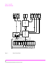
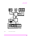
The Test Set’s primary instruments are shown on the left side of Figure 1. There
are two classes of instruments in the Test Set: signal analyzers (RF Analyzer, AF
Analyzer, Oscilloscope, Spectrum Analyzer, Signaling Decoder) and signal
sources (RF Generator, AF Generator #1, AF Generator #2/Signaling Encoder).
The Test Set’s measurement capability can be extended by adding application
specific “top boxes” such as the Agilent 83201A Dual Mode Cellular Adapter.
Since so many instruments are integrated into the Test Set, it is not feasible to
have an actual “front panel” for each instrument. Therefore, each instrument’s
front panel is maintained in firmware and is displayed on the CRT whenever the
instrument is selected. Only one instrument front panel can be displayed on the
CRT at any given time (up to four measurement results can be displayed
simultaneously if desired). Just as with stand alone instruments, instrument front
panels in the Test Set can contain instrument setting information, measurement
result(s), or data input from the DUT.
Using the Test Set in Manual Control mode is very analogous to using a set of
bench or rack-mounted test equipment. To obtain a measurement result with a
bench or racked system, the desired measurement must be “active.” For example,
if an RF power meter is in the bench or racked system and the user wishes to
measure the power of an RF carrier they must turn the power meter on, and look at
the front panel to see the measurement result. Other instruments in the system
may be turned off but this would not prevent the operator from measuring the RF
power.
Conceptually, the same is true for the Test Set. In order to make a measurement or
input data from a DUT, the desired measurement field or data field must be
“active.” This is done by using the front panel keypad/rotary knob to select the
instrument whose front panel contains the desired measurement or data field and
making sure that the desired measurement or data field is turned ON.
Figure 1 shows that instrument selection is handled by the To Screen control
hardware which routes the selected instrument’s front panel to the CRT for
display. Once an instrument’s front panel is displayed on the CRT, the user can
manipulate the instrument settings, such as turning a specific measurement or data
field on or off, using the keypad/rotary knob.
Figure 1 also shows that instrument
setup is handled by the Instrument Control hardware which routes setup
information from the front panel to the individual instruments.
A GPIB/RS-232/Parallel Printer interface capability is available in the Test Set. In
Manual Control mode this provides the capability of connecting an external
GPIB, serial, or parallel printer to the Test Set so that display screens can be
printed.