


Greensmaster 3320/3420 Hydraulic SystemPage 5 -- 39
The lower cutting units relief valve (RV) pressure test
should be performed to make sure that the relief pres-
sure for lowering the cutting units is correct.
Procedure for Lower Cutting Units Relief Valve (R
V)
Pressure
Test:
1. Make sure hydraulic oil is at normal operating tem-
peraturebyoperatingthe machinefor approximatelyten
(10) minutes.
2. Parkmachineon alevelsurface withthe cuttingunits
lowered. Make sure engine is off and the parking brake
is engaged. Make sure the hydraulic tank is full.
CAUTION
Prevent personal injury and/or damage to equip-
ment. Read all WARNINGS, CAUTIONS and Pre-
cautions for Hydraulic Testing at the beginning
of this section.
NOTE: The lower cutting units relief valve is in series
withthetractionchargereliefvalve.Chargereliefpres-
sure will affect the lower cutting units relief pressure.
3. Measure and record charge relief valve pressure
(see Charge Relief Valve Pressure Test in this section).
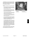
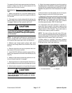
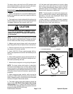
4. Remove right side cover next to operator seat to al-
low access to lift control manifold.
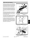
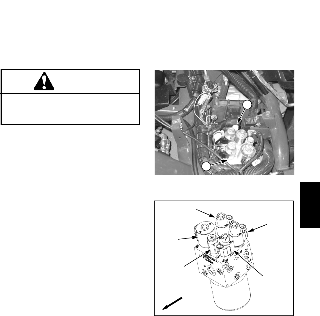
5. Install 1000 PSI (70 bar) pressure gauge with hy-
draulic hoseattached to lift control manifoldtest port (G)
(Fig. 23).
6. After installing pressure gauge, start engine and run
at low idle speed. Check for hydraulic leakage and cor-
rect before proceeding with test.
7. Move throttle soengine isrunning at high idle speed.
NOTE: The lower cutting units function is electrically
timed and automatically turns off after approximately
three (3) seconds. While performing this hydraulic test,
if relief pressure cannot be determined within the LOW-
ER function three (3) second timeframe, repeat this test
procedure.
8. Watch pressure gauge carefully while moving the
joystick to LOWER and note pressure that relief valve
opens. Release joystick, move throttle to low idle speed
and shut off engine. Record test results.
9. The lower cutting units relief pressure should be
approximately 400 PSI (27.6 bar) h igher than charge
relief pressure (e.g. if charge relief valve pressure is
125 PSI (8.6 bar), the lower relief valve pressure should
be approximately 525 PSI (36.2 bar)).
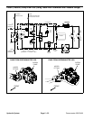
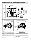
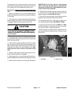
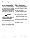
10.If the lower relief valve pressure is incorrect, adjust
lower cutting units relief valve on lift control manifold
(Fig. 24) (see Adjust Manifold Relief Valves in the Ad-
justments section of this Chapter). Retest relief valve
pressure after adjustment is performed.
NOTE: The steering/lift circuit relief valve pressure can
also be measured with pressure gauge positioned as
described in this test (see Steering/Lift Relief Valve
Pressure Test in this section).
11.When testing is complete, disconnect pressure
gauge from lift control manifold test port. Install dust cap
to test port fitting. Install right side cover.
1. Lift control manifold 2. Test port
Figure 23
2
1
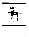
Figure 24
FRONT
S3
S1
S4
RELIEF
VALVE (RV)
S2
LIFT CONTROL
MANIFOLD
Hydraulic
System