


Greensmaster 3320/3420Page 6 -- 4Electrical System
Electrical System Operation
GreensmasterTriFlexHybrid machines usetwo (2)sep-
arate electrical systems. Most machine functions oper-
ate on a typical 12 volt DC system. The second system
exists tooperate theelectric cuttingreels andis a 48volt
DC electrical system. Basic information about the two
systems is included below.
12 Volt DC System Operation
Engine electrical components, machine operation
switches, hydraulic solenoid coils and the machine TEC
electroniccontroller areallincluded inthe 12voltsystem
on Greensmaster TriFlex Hybrid machines. A 1 2 volt
battery on the left side of the machine provides system
electrical power.Circuit protection for the 12volt system
includes two (2) fuse blocks and several fusible links.
Information about electrical components in the 12 volt
system is included in the Component Testing section of
this chapter.
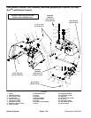
Electric Reel Drive System (48 Volt DC) Operation
Greensmaster TriFlex Hybrid machines utilize an en-
gine driven generator to supply 48 volt DC electrical
power to a set of three (3) electric motors that drive the
cutting reels. The 48 volt system includes the engine
drivengeneratorassembly,thethree (3)cutting reel mo-
tors, a 48 volt battery p ack, the main contactor and con-
trol modules. Circuit protection for the 48 volt system
includes two (2) fuses.
Thegenerator isa 48VDC, 5400 watt,air cooled,brush-
less, permanent magnet device. The generator has its
own integral invertor and on--board controller. The ma-
chine TEC controller provides generator direction with
communication via the CAN--bus system.
The three (3) cutting reel motors are identical 48 VDC,
1100 watt, brushless, permanent magnet motors. Each
motor has its own integral invertor and on--board con-
troller. The machine TEC controller interfaces the reel
motor via the CAN--bus system.
The battery pack is composed of four (4) 12 volt sealed
batteries connected in series to achieve the necessary
48 VDC. The batteries are included in the system to en-
sure that reels come up to speed quickly when initially
engaged. The batteries are also used as a buffer when
the cutting reels are shut off. As the cutting reels slow to
a stop, they generate electrical power that is absorbed
by the battery pack. The batteries also assist with sys-
tem precharge and diagnostics.
The main contactor exists in the electric reel drive sys-
tem to connect the battery pack with the generator and
reel motor controllers. The generator controller deter-
mines when the main contactor is engaged.
Control for the components in the electric reel drivesys-
tem is handled by integral controllers in the generator
and reel motors along with direction from the TEC ma-
chinecontrollervia theCAN--bus system.SincetheTEC
controller (12 VDC component) sends and receives in-
formation with the generator and reel motors (48 VDC
components), t he CAN--bus circuit needs to communi-
catewith bothsystems. Theisolation moduleisincluded
in the system to allow effective communication while
keeping the two machine electrical systems isolated.
Also, the location ID module exists to identify the loca-
tion of the three (3) cutting reel motors. This allows such
machine features as raising the center cutting unit
slightly later than the front cutting units.
The 48 volt system is an isolated system so the vehicle
frame is notused forany groundconnections in thissys-
tem. A 48V battery disconnect is included on the ma-
chine which can be used to disconnect the cutting unit
motorsfrom theelectricalpower supplyto preventunex-
pected reel motor operation when performing service.
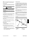
IMPORTANT: When connecting the battery pack in
the 48 volt system, make sure that battery polarity
is carefully checked. System damage can occur if
batteries are not connected correctly.
Information about electrical components in the 48 volt
system is included in the Component Testing section of
this chapter.