


Greensmaster 3320/3420 Hydraulic SystemPage 5 -- 85
5. Remove hoseassemblies andO--rings from hydrau-
lic fittings atthe cylinder. Allow hosesto drain into a suit-
able container.
6. Put c lean caps or plugs on disconnected hoses and
fittings to prevent contamination.
7. Support steering cylinder to prevent it from falling.
8. Remove jam nuts that secure cylinder ball joints to
frame and rear fork assembly.
9. Separate cylinder ball joints from frame and rear
fork. Remove steering cylinder from machine. Locate
and retrieve cylinder spacer (item 10).
10.If necessary, remove hydraulic fittings from steering
cylinder and discard O--rings.
11.If necessary, remove ball joints from steering cylin-
der. Discard removed ball joints.
Installation (Fig. 56)
1. If ball joints were removed from steering cylinder,
press new ball joints into steering cylinder and secure
with retaining rings.
2. If fittings were removed from steering cylinder, lubri-
cate and place new O--rings onto fittings. Install fittings
into cylinder portopenings.Tighten fittings(see Hydrau-
lic Fitting Installation in the General Information section
of this chapter).
3. Thoroughly clean tapered surfaces of steering cylin-
der ball joints and cylinder attachment bores on ma-
chine.
4. Place cylinder spacer (item 10) onto cylinder barrel
ball joint.
5. Insertball joints of cylinder into attachment points on
frame and rear fork assembly.
6. Secure both steering cylinder ball joints to machine
with two (2) jam nuts (item 4). Install first jam nut and
torque from 60 to 80 ft--lb (82 to 108 N--m). Then, while
holding first jam nut withwrench, tighten second jam nut
and torque from 60 to 80 ft--lb (82 to 108 N--m).
7. Remove caps and plugs from disconnected hoses
and fittings.
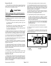
8. Lubricate new O--rings and connect hydraulic hoses
to steering cylinder (Fig. 57). Tighten hose connections
(see Hydraulic Hose and Tube Installation in the Gener-
al Information section of this chapter).
9. Lower and secure tank mount plate assembly (hy-
draulic reservoir, fuel tank and tank mount plate) (see
Tank Mount Plate Assembly in the Service and Repairs
section of Chapter 7 -- Chassis).
10.Check fluid level in hydraulic oil reservoir and adjust
as required.
11.After assembly is completed, operate steering cylin-
derto verifythathydraulichoses and fittings arenot con-
tacted by anything a n d that there are no leaks. Also,
makesurethata clockwiser otation ofthe steeringwheel
turns the r ear wheel for a right turn.
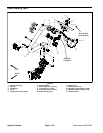
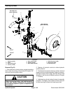
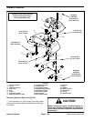
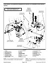
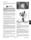
1. Steering cylinder
2. Hyd fitting (2 used)
3. Hyd hose
4. Hyd hose
5. O--ring
6. O--ring
Figure 57
6
5
4
3
2
2
1
FRONT
Hydraulic
System