


Greensmaster 3320/3420
DPA Cutting Units
Page 8 -- 28
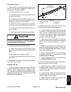
Front Roller
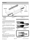
Removal (Fig. 29)
1. Position machine on a clean and level surface, lower
cutting units, stop engine, engageparking brake and re-
move key from the ignition switch.
2. Remove the cutting unit from the machine and place
on a level working surface. Use appropriate support to
raise front roller from work surface.
3. Loosen cap screw (item 1) that secures the front roll-
er shaft to each front height--of--cut arm.
4. On one of the height--of--cut arms, remove HOC nut
(item 7), HOCwasher (item 6)and plow bolt(item 4)that
secure HOC arm to the cutting unit side plate. Remove
the HOC arm from the cutting unit.
5. Slide the front roller assembly from the remaining
HOC arm on the cutting unit.
6. If necessary, remove the second HOC arm from the
cutting unit.
Installation (Fig. 29)
1. Place cutting unit on a level working surface and use
appropriate support to support front of cutting unit.
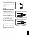
2. Inspect condition of HOC screws (item 5) in both
HOC arms. If necessary, apply antiseize lubricant to
threadsof newHOC screw.Thread new HOC screw into
HOC arm.
NOTE: When assembling HOC arms to side plates,
make sure that ring on HOC screw fits into the notch on
thesideplate.
3. If both HOC arms were removed from cutting unit
side plate,position one of thearms to side plate. Secure
arm to side plate with plow bolt (item 4), HOC washer
(item 6) and HOC nut (item 7). Tab on HOC washer
should be positioned into HOC arm slot and orientated
down toward the roller.
4. Slidefront roller shaft into armattached to thecutting
unit. Slide second HOC arm onto the other end of roller
shaft. Secure second arm to cutting unit side plate with
plow bolt (item 4), HOC washer (item 6) and HOC nut
(item 7).
5. Center front roller to the cutting reel and secure to
HOC arms with cap screws (item 1).
6. Adjust cutting unit (see Cutting Unit Operator’s
Manual).
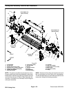
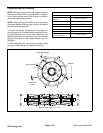
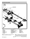
1. Cap screw
2. HOC arm
3. Front roller assembly
4. Plow bolt
5. HOC screw
6. HOC washer
7. HOC nut
Figure 29
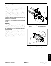
Antiseize
Lubricant
1
2
3
4
5
6
7
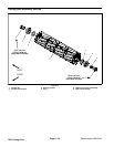
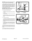
1. Front roller assembly
2. HOC arm
3. HOC screw
4. HOC washer & nut
Figure 30
2
1
3
4