


Greensmaster 3320/3420Page 6 -- 26Electrical System
Hand Held Diagnostic Display
Your Greensmaster is equipped with a Toro Electronic
Controller(TEC) whichcontrolsmachine electricalfunc-
tions. The controller monitors various input switches
(e.g. ignition switch, seat switch, etc.) and energizes
outputs to actuate solenoids or relays for the requested
machine function.
For the controller to properly control the machine, each
of the input switches, output solenoids and relays must
be connected and functioning properly.
The Hand Held Diagnostic Display (see Special Tools in
this chapter) is atool to help the technician verify correct
electrical functions of the machine.
IMPORTANT: The Hand Held Diagnostic Display
must not be left connected to the machine. It is not
designed to withstand the environment of the ma-
chine’s every day use. When use of Diagnostic Dis-
play is completed, disconnect it from the machine
and install protective cap to wire harness connec -
tor.Store Diagnostic Displayin adry,secure,indoor
location and not on machine.
CAUTION
The interlock switches are for the protection of
the operator and bystanders and to ensure cor-
rect operation of the machine. Do not bypass or
disconnect interlock switches. Check the opera-
tion of the interlock switchesdaily for proper op-
eration. Replace any malfunctioning switches
before operating the machine.
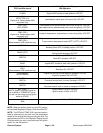
Verify Diagnostic Display Input Functions
1. Park machine on a level surface, lower the cutting
units, engage the parking brake and stop the engine.
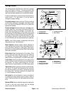
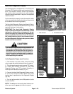
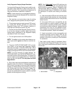
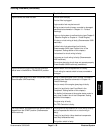
2. Tiltand support operators eat toaccess TEC control-
ler. Locate wire harness connector for Hand Held
Diagnostic Display near TEC controller. Carefully re-
move cap from harness connector (Fig. 27).
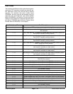
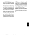
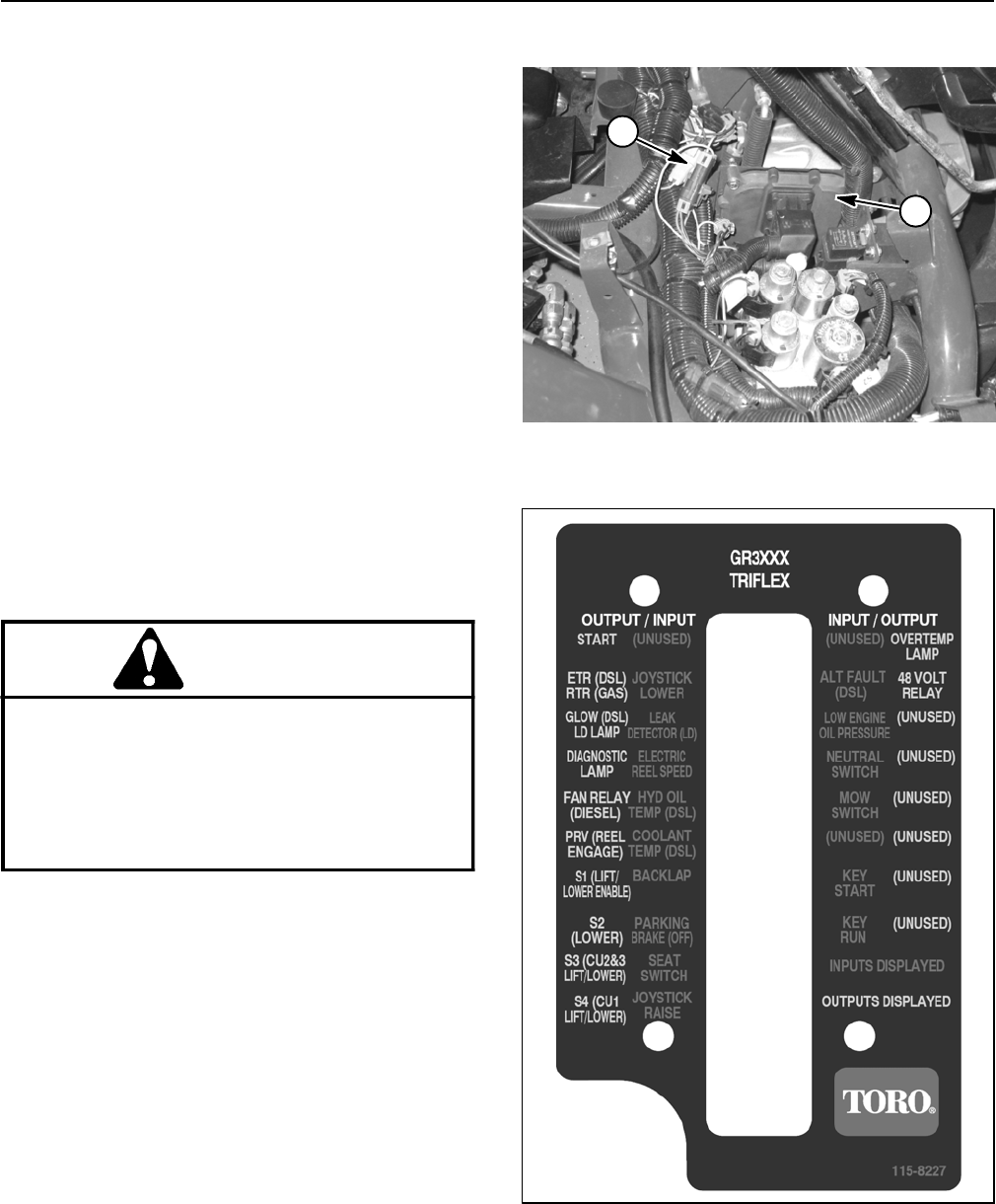
3. Connect the Hand Held Diagnostic Display connec-
tor to the wire harness connector. Make sure correct
overlay decal is positioned on the Diagnostic Display
(Fig. 28).
4. Turn the ignition switch to the RUN position, but do
not start machine.
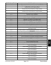
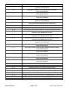
NOTE: The red text on the overlay decal refers to con-
troller inputs and the green text refers to outputs.
1. TEC controller 2. Hand held connector
Figure 27
1
2
Figure 28
OVERLAY
DIAGNOSTIC
DISPLAY
115--8227
HAND HELD