


Greensmaster 3320/3420 Hydraulic SystemPage 5 -- 89
2. Ifmachineis equipped withoptionalTurfGuardian
TM
Leak Detector System, remove leak detector tank and
solenoid valve a ssembly (see Leak Detector Tank (Ma-
chines Equipped with Optional Turf Guardian
TM
Leak
DetectorSystem) andLeakDetector Solenoid Valve As-
sembly (Machines Equipped with Optional Turf Guar-
dian
TM
Leak Detector System) in this section).
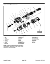
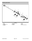
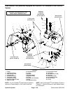
3. Remove four (4) cap screws (item 7), flat washers
(item 9), neoprene washers (item 8) and spacers (item
20) that secure tank cover to hydraulic reservoir.
4. Loosen hose clamp and disconnect overflow hose
(item 10) from tank cover barb.
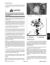
NOTE: On Greensmaster 3320 machines with serial
number above 312000000, the fuel system carbon can-
ister is attached to thereservoir cover. SeeFuel System
Carbon Canister (Serial Number Above 312000000) in
theService andRepairs sectionof Chapter 3 -- Gasoline
for information on disconnecting the canister.
5. Remove tank cover from machine.
6. Completely drain hydraulic oil from hydraulic reser-
voir through gear pumpsuction hoseinto a suitable con-
tainer.
7. Labelhydraulic reservoir hydraulic hoses for assem-
bly purposes. Thoroughly clean hydraulic hose ends
priorto disconnectingthe hosesfrom hydraulicreservoir
fittings.
8. Remove hoseassemblies andO--rings from hydrau-
lic reservoir fittings. Allow hoses to drain into a suitable
container.
9. Put c lean caps or plugs on disconnected hoses and
fittings to prevent contamination.
10.To allow easier access to fasteners that secure hy-
draulic reservoir, raise and support tank mount plate as-
sembly (hydraulic reservoir, fuel tank and tank mount
plate) (see Tank Mount Plate Assembly in the Service
and Repairs section of Chapter 7 -- Chassis).
11.Remove four (4) cap screws (item 14), flat washers
(item 13) and flange bushings (item 12) that secure the
hydraulic reservoir (item 3) to the tank mount plate.
12.Remove hydraulic reservoir from machine.
13.If hydraulic fittings are to be removed from reservoir,
mark fitting orientation to allow correct assembly. Re-
move hydraulic fittings and plugs from hydraulic reser-
voir as needed. Discard O--rings from removed fittings
and plugs.
14.Clean hydraulic reservoir and reservoir components
with clean solvent. Inspect reservoir for leaks, cracks or
other damage.
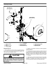
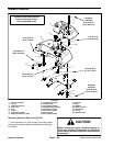
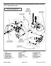
Installing Hydraulic Reservoir (Fig. 59)
IMPORTANT: When installing tank cover and reser-
voir to machine, do not over-- tighten cap screws.
Threads in reservoir may become damaged.
1. Lubricate and place new O--rings onto all removed
fittings and plugs. Install fittings and plugs into reservoir
openings. U se marks made during the removal process
tocorrectlyorientatefittings.RefertoFigure59forres-
ervoir fitting and plug installation torque specifications.
2. Position hydraulic reservoir onto the tank mount
plate.
3. Apply antiseize lubricant to threads of four (4) cap
screws (item 14). Secure hydraulic reservoir to the tank
mount plate with four (4) cap screws, flat washers (item
13) and flange bushings (item 12). Torque cap screws
from 30 to 50 in--lb (3.4 to 5.6 N--m).
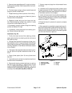
4. Lower and secure tank mount plate assembly (hy-
draulic reservoir, fuel tank and tank mount plate) (see
Tank Mount Plate Assembly in the Service and Repairs
section of Chapter 7 -- Chassis).
5. Remove caps and plugs from disconnected hydrau-
lic hoses and reservoir fittings.
6. Lubricateand positionnew O--rings tofittings onres-
ervoir. Use labels placed during the removal process to
properly install hydraulic lines to reservoir fittings (see
Hydraulic Hose and Tube Installation in the General In -
formation section of this chapter).
7. Ifmachineis equippedwith optionalTurfGuardian
TM
Leak Detector System, install leak detector tank and so-
lenoid valve assembly (see Leak Detector Tank (Ma-
chines Equipped with Optional Turf Guardian
TM
Leak
DetectorSystem)a nd Leak DetectorSolenoidValveAs-
sembly (Machines Equipped with Optional Turf Guar-
dian
TM
Leak Detector System) in this section).
NOTE: On Greensmaster machineswith serialnumber
above 312000000, see Fuel System Carbon Canister
(Serial Number Above 312000000) in the Service and
Repairs section of Chapter 3 -- Gasoline for information
on connecting the fuel system carbon canister.
8. Position tank cover to top of hydraulic reservoir.
9. Connect overflow hose (item 10) to tank cover barb
andsecurewithhoseclamp.
10.Apply antiseize lubricant to threads of four (4) cap
screws(item 7).Secure tank coverto hydraulicreservoir
with four (4) spacers (item 20), cap screws (item 7), flat
washers (item 9) and neoprene washers (item 8).
Torque cap screwsfrom30 to50 in--lb (3.4to 5.6N--m).
11.Fill hydraulic reservoir with new hydraulic oil.
Hydraulic
System