


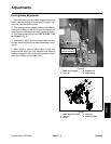
Greensmaster 3320/3420 Page 7 -- 9 Chassis
NOTE: If desired, the complete brake assembly can be
removed fromthe machinefor disassembly(see step 11
below).
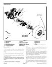
9. Remove shoe springs from brake shoes (Fig. 9).
10.Remove shoe hold down cups and springs. Remove
brakeshoesandhold downpinsfrom backingplate(Fig.
9).
11.If n ecessary, remove backing plate from machine by
removing four (4) cap screws (item 6).
12.If necessary, press wheel studs from brake drum as-
sembly to allow separation of brake drum and wheel
hub.
Installation (Fig. 7)
1. Remove rust and debris from all parts with a wire
brush prior to installation. Clean all parts. Inspect brake
shoe contact surfaces of the brake drum for excessive
wear. Replace any worn or damaged parts.
2. Ifbacking platewas removedfrom machine,position
backing plate to wheel motor with brake lever inserted
into slot of brake lever tab. Secure backing plate to
wheel motor with four (4) cap screws (item 6).
3. Lightly lubricate brake shoe pivot points with general
purpose grease.
4. Position one brake shoe to the backing plate. Install
brake hold down pin and secure with hold down spring
and cup (Fig. 9). Repeat for second brake shoe.
5. Install shoe springs to brake shoes (Fig. 9). Make
sure that brake shoes are properly positioned to pivot
and actuator points.
6. If brake drum was separated from wheel hub, align
holes in drum and hub. Secure hub to drum by pressing
wheel studs into assembly. Make sure that stud shoul-
ders are fully pressed against drum surface.
IMPORTANT: Before brake drum assembly is
installed, thoroughly clean tapers of wheel hub and
wheel motor shaft. Make sure that tapers are free of
grease, oil and dirt. Do not use antiseize lubricant
when installing drum assembly.
7. Mount key in the wheel motor shaft, then install the
brake drum assembly onto the wheel motor shaft.
8. Install new lock nut (item 7) onto the wheel motor
shaft to secure brake drum assembly.
9. Position brake cable end to brake actuator lever.Se-
cure cable to actuator lever with clevis pin and e--ring
(Fig. 8).
10.Install front wheel assembly (see Wheel Installation
in this section).
11.Lower machine to ground.
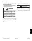
Failure t o maintain proper wheel lug nut and
wheel hub lock nut torque could result in failure
or loss of wheeland may result in personal injury.
WARNING
12.Torque lug nuts evenly in a crossing pattern from 65
to 85 ft--lb (89 to 115 N--m). Torque lock nut (item 17)
that secures wheel hub from 250 to 400 ft--lb (339 to
542 N--m).
13.Check and adjust parking brake.
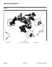
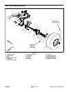
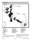
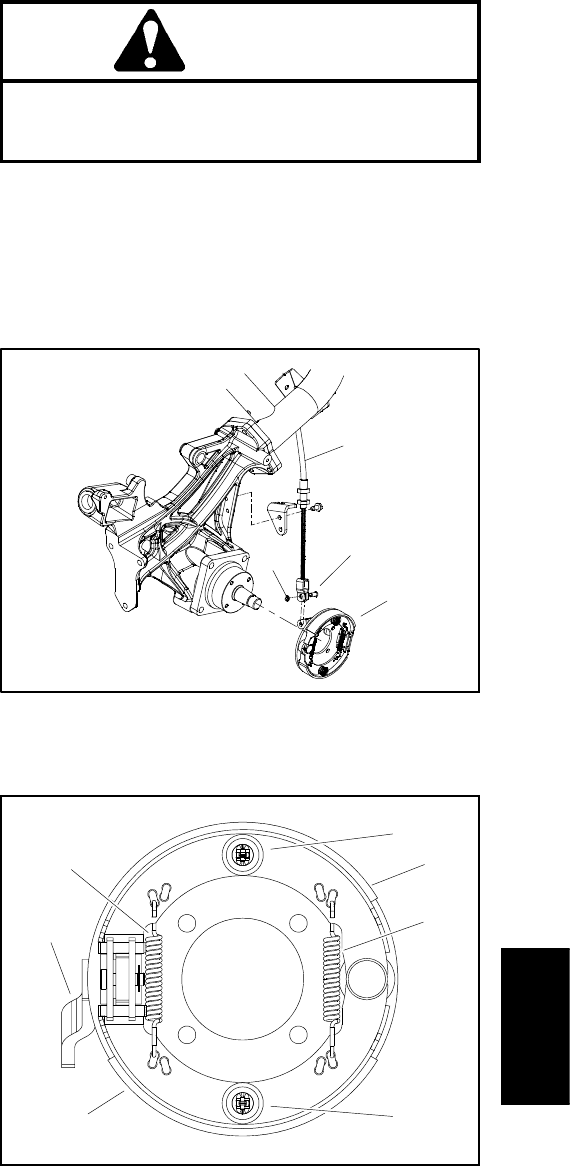
1. Brake cable (RH shown)
2. Clevis pin
3. E--ring
4. Brake assembly
Figure 8
1
2
4
3
1. Brake shoe
2. Cup, spring and pin
3. Shoe spring
4. Actuator lever
Figure 9
1
2
4
3
1
2
3
Chassis