


Greensmaster 3320/3420Page 6 -- 50Electrical System
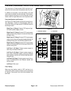
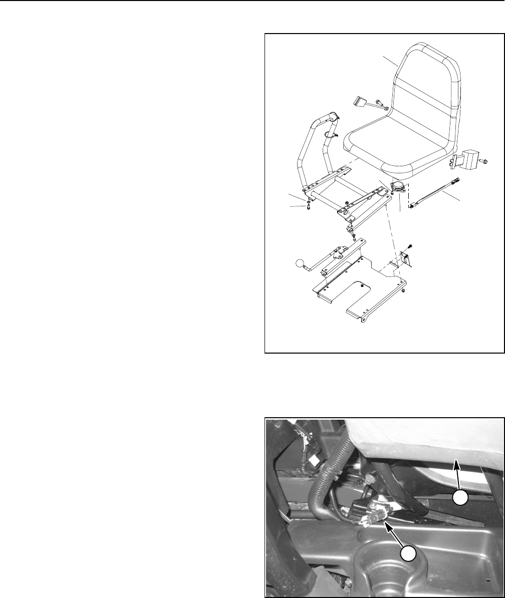
Seat Switch
The seat switch is normally open and closes when the
operator is on the seat. If the Functional Control Lever
is moved out of neutral (neutral switch opens) and the
operator raises out of the seat, the engine will stop. The
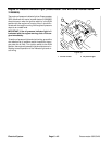
seat switch and its electrical connector are located di-
rectly under the seat (Fig. 55).
Testing
1. Park machine on level surface, lower cutting units,
stop engine, apply parking brake and remove key from
ignition switch.
2. Before disconnecting the seat switch for testing, the
switch and its circuit wiring should be tested as a TEC
electrical input using the Hand Held Diagnostic Display
(see Hand Held Diagnostic Display in the Troubleshoot-
ingsection of thischapter)or InfoCenter Display(see In-
foCenter Display in this chapter). If input testing verifies
that the seat switch and circuit wiring are functioning
correctly, no further seat switch testing is necessary. If,
however, input testing determines that the seat switch
and circuit wiring are not functioning correctly, proceed
with the following seat switch testing procedure.
3. Make sure ignition switch is in the OFF position.
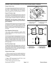
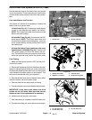
4. Disconnect seat switch wire harness connector from
machine wire harness at rear of operator seat (Fig. 56).
5. Check the continuity of the switch by connecting a
multimeter (ohms setting) across the seat switch wire
harness connector terminals.
6. With no pressure on the seat, there should be no
continuity (open) between the harness terminals.
7. Press directly onto the seat switch through the seat
cushion. There should be continuity (closed) between
the harness terminals as the seat cushion approaches
the bottom of its travel.
8. If continuity checks determine faulty seat switch op-
eration,check seatswitch wireharnessforproblemsbe-
fore replacing seat switch.
9. Ifthe seatswitch testscorrectly anda circuit problem
still exists, check machine wire harness (see Electrical
Schematic and Wire Harness Drawings in Chapter 10 --
Foldout Drawings).
10.After seat switch testing is complete, connect seat
switchwireharness connectorto machinewireharness.
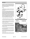
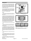
1. Operator seat
2. Seat switch
3. Cap screw (2 used)
4. Seat switch harness
5. Flat washer (4 used)
6. Cap screw (4 used)
Figure 55
1
2
3
4
5
6
STANDARD SEAT ASSEMBLY SHOWN
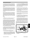
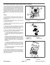
1. Operator seat 2. Seat switch connector
Figure 56
1
2