


Greensmaster 3320/3420 Page 6 -- 43 Electrical System
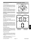
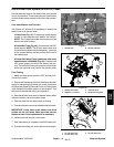
Indicator Lights (Greensmaster 3420 with Serial Number Below 312000000)
Charge Indicator Light
The chargeindicator light shouldcome onwhentheigni-
tionswitch isin theRUNpositionwith theengine notrun-
ning. Also, it should illuminate with an improperly
operating charging circuit while the engine is running.
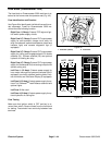
Engine Oil Pressure Light
The engine oil pressure light should come on when the
ignition switch is in the RUN position with the engine not
running. Also, it should illuminate with the engine run-
ning if the engine oil pressure drops to an unsafe level.
IMPORTANT: If the oil pressure indicator light is il -
luminated with the engine running, shut off the en-
gine immediately.
To testtheo il pressurelight andcircuit wiring,ground the
wire attached to oil pressure switch located on the en-
gine near the oil filter. Turn ignition switch to the RUN
position;the engineoil pressure lightshouldcome onin-
dicating correct operation of the indicator light and cir-
cuit wiring.
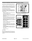
High Temperature Warning Light
If the engine coolant temperature reaches 220
o
F
(105
o
C) (approximate), the high temperature warning
light will come on.
To testthe high temperaturewarninglightand circuit wir-
ing, turn ignition switch to the RUN position and ground
thewireattachedtohightemperaturewarningswitchlo-
cated on the engine water pump housing (see High
Temperature Warning Switch in this section). The high
temperature warning light should illuminate when the
wire is grounded.
Glow Plug Indicator Light
The g low plug indicator light should come on when the
ignitionswitchis placedin theRUNpositionprior toplac-
ing the ignition switch in START. The light should stay lit
for a pproximately six (6) seconds while the ignition
switch is left in the RUN position.
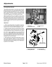
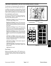
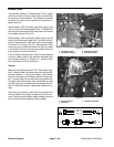
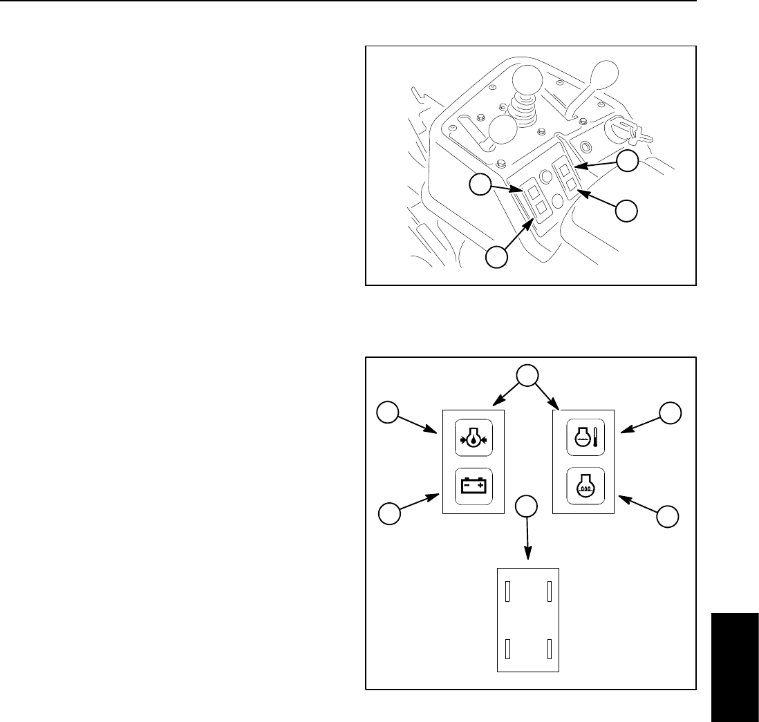
Testing Indicator Lights
1. Remove console cover from console assembly to
gain accessto indicator lights (seeControl ConsoleDis-
assembly in the Service and Repairs section of Chapter
7--Chassis).
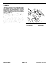
2. Apply 12 VDC to terminals 1A and 2A (Fig. 4 1) and
ground terminals 1B and 2B (Fig. 41).
3. Both indicator lights should illuminate.
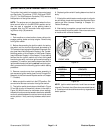
1. Charge indicator light
2. Oil pressure light
3. High temp warning light
4. Glow plug light
Figure 40
1
3
2
4
Figure 41
1. Charge indicator
2. Engine oil pressure
3. High temperature
4. Glow plug indicator
5. Indicator light front
6. Indicator light back
1A (+)
2A (+)2B (--)
1B (--)
4
3
5
2
1
6
Electrical
System