


Greensmaster 3320/3420 Page 6 -- 97 Electrical System
4. Locateand unplug two (2) electrical connectors from
motor cable to machine wire harness.
5. Route m otor cable o ut of wire form on cutting unit
suspension.
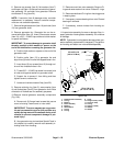
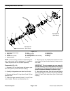
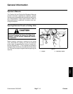
6. Remove cutting reel motor from the cutting unit:
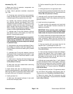
A. Push the motor clamp out of the slots on the mo-
tor mounttoward the cutting unit sideplate (Fig. 111).
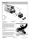
B. Slide cutting reel motor from cutting unit (Fig.
112).
7. If necessary, remove two (2) retaining rings that se-
cure motor mount (item 4) to reel motor. Remove motor
mount from motor.
Installation (Fig. 109)
1. If motor mount was removed from motor, position
motormount tocuttingreelm otor flangeandsecure with
two (2) retaining rings.
2. Install cutting reel motor to the cutting unit:
A. Coat splines of cutting reel motors haft with clean
grease.
B. Align cutting reel motor shaft splines with splines
in cutting reel. Slide reel motor into cutting unit side
plate (Fig. 112).
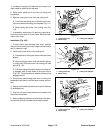
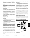
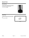
C. Pull motorclamp toward themotor until clamp ful-
ly engages slots on both sides of the motor mount
(Fig. 113). There should be anaudible clickas clamp
engages mount.
3. Route motor cable through wire form on cutting unit
suspension and then to machine wire harness connec-
tors.
4. Secure motor cable to brackets on machine with two
(2) bulkhead nuts.
5. Plug two (2) motor cable electrical connectors into
machine wire harness.
6. Aftercompletinginstallationof allcuttingunit motors,
connect the cutting unit power disconnect couplers.
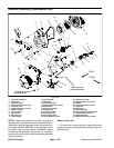
1. Cutting reel motor
2. Motor clamp
3. Cutting unit sideplate
Figure 111
2
1
3
Figure 112
2
1
3
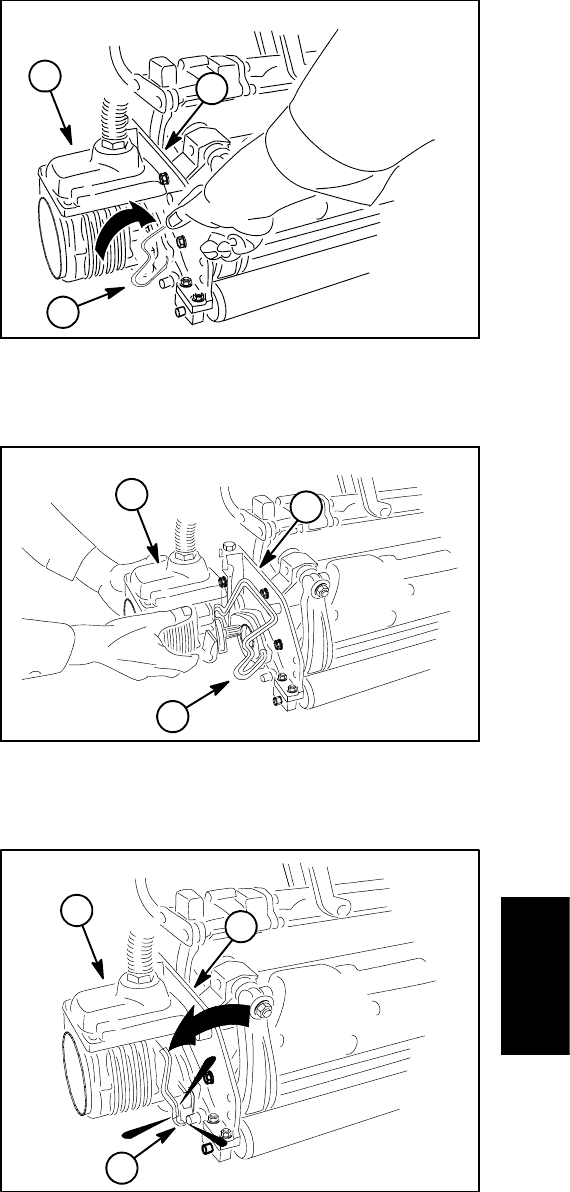
1. Cutting reel motor
2. Motor clamp
3. Cutting unit sideplate
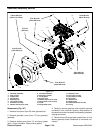
Figure 113
1. Cutting reel motor
2. Motor clamp
3. Cutting unit sideplate
2
1
3
Electrical
System