


Greensmaster 3320/3420 Hydraulic SystemPage 5 -- 71
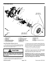
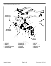
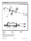
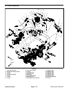
Lift Cylinder Removal (Fig. 49)
1. Park the machine on a level surface, engage the
parking brake, lower the cutting units and stop the en-
gine.
CAUTION
Before continuing further, read and become fa-
miliar with General Precautions for Removing
and Installing Hydraulic System Components in
this section.
2. Thoroughlycleanhydraulichose endsandfittings on
lift cylinder to prevent hydraulic system contamination.
3. Label hydraulic hoses for assembly purposes.
WARNING
Make sure that cutting units are fully lowered be-
fore loosening hydraulic lines at lift cylinder. If
cutting units are raised as lift cylinder hoses are
loosened, cutting units may drop unexpectedly.
4. Disconnect hydraulic hoses from fittings on the lift
cylinder. Allow hoses to drain into a suitable container.
Install clean caps or plugs to hoses and cylinder fittings
to prevent contamination.
5. Removerue ring(item 18),washer (item17) and cle-
vis pin (item 9) that secure cylinder rod clevis to cutting
unit suspension. Separate lift cylinder clevis from sus-
pension.
6. Support lift cylinder to prevent it from dropping. Sep-
arate lift cylinder from frame:
A. For front (#2 or #3 cutting unit) lift cylinder, re-
move lock nut (item 6) and tapered pin (item 4) that
secure lift cylinder to frame.
B. For center (#1 cutting unit) lift cylinder, remove
flange nut (item 8) and flange head screw (item 13)
that secure pivot pin (item 10) to frame. Slide pivot
pin from frame and lift cylinder.
7. Remove hydraulic cylinder from machine.
8. If hydraulic fittings are to be removed from lift cylin-
der, mark fitting orientation to allow correct assembly.
Remove hydraulic fittings and O--rings from cylinder.
Discard removed O--rings.
9. Inspect threads and sealing surfaces of fittings and
lift cylinder ports. Replace components if damage is
found.
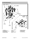
Lift Cylinder Installation (Fig. 49)
1. If fittings were removed from lift cylinder, lubricate
and place new O--rings onto fittings. Install fittings into
cylinder ports making sure that fitting orientation is as
notedduring removal. Tighten fittings (seeHydraulicFit-
tingInstallation inthe GeneralInformationsec tion ofthis
chapter).
2. Position barrel end of lift cylinder to frame attach-
ment point. Separate lift cylinder from frame:
A. For front (#2 or #3 cutting unit) lift cylinder, make
sure that tapered surfaces of pin (item 4) and frame
mount are thoroughly clean. Slide tapered pin
through lift cylinder and frame. Secure assembly
with lock nut (item 6).
B. For center (#1 cutting unit) lift cylinder, slide pivot
pin (item 10) through frame and lift cylinder. Secure
pivot pin to frame with flange head screw (item 13)
and flange nut (item 8).
3. Position clevis of the lift cylinder to the cutting unit
suspension. Secure cylinder clevis to suspension with
clevis pin (item 9), washer (item 17) and rue ring (item
18).
4. Positionclevis of thehydraulic cylinder tothe lift arm.
Install clevis pin and cotter pin through cylinder clevis.
5. Remove caps and plugs from disconnected hydrau-
lic hoses and lift cylinder fittings.
6. Usinglabels placedduring liftcylinder removal,lubri-
cate new O--rings and connect hydraulic hoses to cylin-
der. Tighten hose connections (see Hydraulic Hose and
Tube Installation in the General Information section of
this chapter).
7. Check oil level in hydraulic reservoir and add correct
oil if necessary.
8. Follow Hydraulic System Start--up procedures (see
Hydraulic System Start--up in this section).
Hydraulic
System