


Greensmaster 3320/3420Page 6 -- 40Electrical System
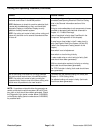
Component Testing
For accurate resistance and/or continuity checks, elec-
trically disconnect the component being tested from the
circuit (e.g. unplug the ignition switch connector before
doing a continuity check).
NOTE: For engine component testing information, re-
fer to the appropriate engine service manual (Briggs &
Stratton R epair Manual or Kubota Workshop Manual).
CAUTION
When testing electrical components for continu-
ity with a multimeter (ohms setting), make sure
that power to the circuit has been disconnected.
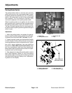
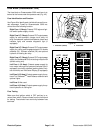
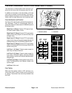
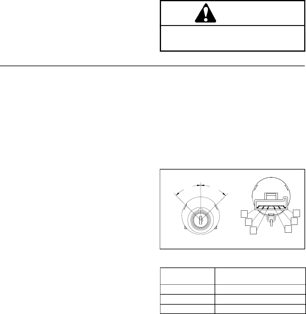
Ignition Switch (Serial Number Below 312000000)
The ignition (key) switch is located on the control panel
and has three (3) positions: STOP, RUN and START
(Fig. 35). The To ro Electronic Controller (TEC) monitors
the operation of the ignition switch.
NOTE: The engine can only be started when the func-
tional control lever is in the NEUTRAL position and ei-
ther the seat is occupied or the parking brake is
engaged. Also, the TEC controller limits engine crank-
ing time to thirty (30) seconds.
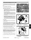
Testing
1. Park machine on a level surface, lower cutting units,
engage parking brake and stop engine. Remove key
from ignition switch.
2. Before disconnecting the ignition switch for testing,
the switch and its circuit wiring should be tested as a
TECelectricalinputusing theHandHeld DiagnosticDis-
play (see Hand Held Diagnostic Display in the Trouble-
shooting section of this chapter). If input testing verifies
that the ignition switch and circuit wiring are functioning
correctly, no further ignition switch testing is necessary.
If, however, input testing determines that the ignition
switch and circuit wiring are not functioning correctly,
proceed with the following ignition switch testing proce-
dure.
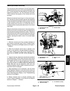
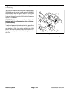
3. Remove console cover from console assembly to
gain access to ignition switch (see Control Console Dis-
assembly in the Service and Repairs section of Chapter
7 -- Chassis).
4. Make sure ignition switch is in the OFF position. Dis-
connect wire harness connector from ignition switch.
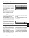
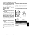
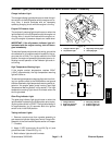
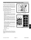
5. Theignitionswitchterminals are identified in Figure
35 and the circuitry of the switch is shown in the chart in
Figure 36. With the use of a multimeter (ohms setting),
the switch functions can be tested to determine whether
continuity exists between the various terminals for each
switch position. Verify continuity between switch termi-
nals.
6. Replace ignition switch if testing determines that it is
faulty.
7. Ifthe ignitionswitch testscorrectly anda circuit prob-
lem still exists,check wire harness (see Electrical Sche-
matics and Wire Harness Drawings in Chapter 10 --
Foldout Drawings).
8. After testing is complete, connect machine wire har-
ness connector to ignition switch. Secure console cover
to machine with removed fasteners.
Figure 35
REAR VIEW
FRONT VIEW
A
B
C
D
E
F
START
STOP
RUN
45
o
45
o
SWITCH
POSITION
CIRCUITS
STOP NONE
RUN B+C+F, D+E
START A+B+C
Figure 36