


Rev. A
Greensmaster 3320/3420 Page 6 - 63 Electrical System
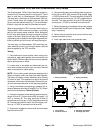
CAN- bus Termination Resistors
System communication between electrical components
on Greensmaster Hybrid TriFlex machines is accom-
plished on two (2) CAN- bus communication systems.
Two (2) specially designed, twisted cables form the bus
for both of the networks used on the Hybrid machines.
These wires provide the data pathways between ma-
chine components. At the ends of the twistedpair of bus
cables are 120 ohm termination resistors.
The resistors plug into the wire harness in the following
areas:
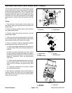
A. The two (2) termination resistors for the main
electrical system on Greensmaster machines are lo-
cated near the hydraulic lift control manifold under
the right side cover next to the operator seat.
B. The two (2) termination resistors for the E- Reels
electrical circuit are located near the wire harness
connectors for the RH and LH cutting reel motors.
NOTE: Refer to the Electrical Sch ematics and Wire
HarnessDrawings inChapter 10 - Foldout Drawingsfor
additional information on termination resistor locations
and wire connections.
IMPORTANT: The termination resistors at the ends
of the bus cables are required for proper electrical
system operation.
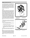
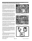
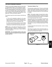
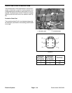
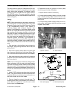
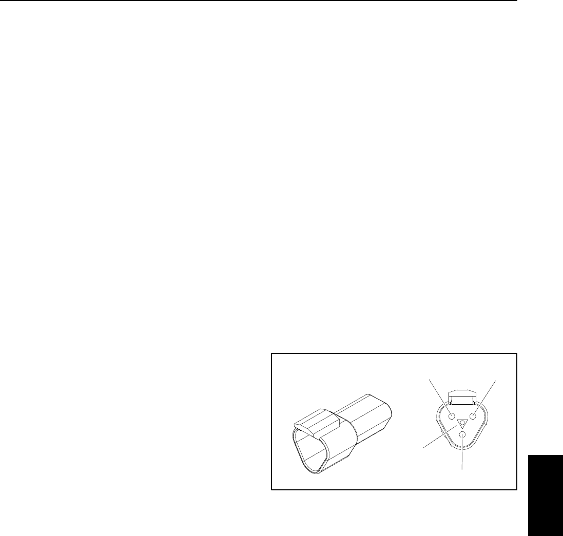
Termination Resistor Test
The termination resistors (Fig. 79) c an be individually
tested using a digital multimeter (ohms setting). Locate
resistor and remove cable tie that secures resistor to
wire harness. Unplug the resistor from the wire harness
for testing.
NOTE: The insulator wedge in the termination resistor
is blue for identification purposes. There also is a center
keywaytopreventthet ermination resistorfrom plugging
into the wrong wire harness connector.
Use a digital multimeter (ohms setting) t o measure the
resistance value for the termination resistor. There
should be 120 ohms resistance between terminals A
and B. Refer to Fig. 79 to determine terminal locations.
Terminal C is not used on Greensmaster Hybrid TriFlex
machines.
If testing determines that termination resistor is faulty,
replace resistor.
After testing is complete, make sure that termination re-
sistor is fully installed into wire harness connector and
securedtowireharnesswithcabletie.
Figure 79
Termination
Resistor
A
B
C
Keyway
Electrical
System