


Greensmaster 3320/3420Page 6 - 72Electrical System
Turf Guardian
TM
Leak Detector Oil Level Sensor (If Equipped)
NOTE: The Turf Guardian
TM
Leak Detector System is
optional on Greensmaster TriFlex Hybrid machines.
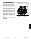
The leak detector oil level sensor closely monitors the
hydraulic fluid level in the main hydraulic reservoir. The
sensor is open when the sensor float is in the raised
positionand closedwhen thefloat isin theloweredposi-
tion. See Turf Guardian
TM
Leak Detector System Op-
eration in this chapter for information regarding Leak
Detector System operation.
Oil Level Sensor Testing
NOTE: On Greensmaster 3320 machines, the leak de-
tector oil level sensor is an input for the TEC controller.
Before disconnecting the oil level sensor for testing on
a Greensmaster 3320, the sensor and its circuit wiring
should be tested as a TEC electrical input using Hand
HeldDiagnostic Display (see Hand HeldDiagnosticDis-
play in the Troubleshooting section of this chapter) or
InfoCenter Display (see InfoCenter Display in this
chapter). If input testing verifies that the oil level sensor
and circuit wiring are functioning correctly, no further
sensor testing is necessary. If, however, input testing
determines that th eoil levelsensor andcircuit wiringare
not functioning correctly, proceed with the following
sensor testing procedure.
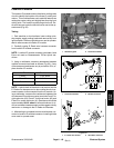
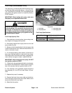
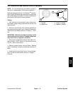
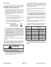
1. If the oil level sensor is connected to the main wire
harness, remove hydraulic tank cap from filler neck of
hydraulic reservoir. Start the engine. Insert a clean rod
or screw driver into filler neck and gently p ush down on
sensor float (Fig. 95). Alarm should sound and console
leak detector indicator light should illuminate after a one
(1) second time delay.
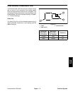
2. If the oil level sensor is removed or disconnected
from the main wire harness, connect a continuity tester
acrossthe sensor wireterminals. There should beconti-
nuity (low resistance) across the sensor connector ter-
minals when the float is pushed down. There should not
be continuity (infiniteresistance) across the sensorcon-
nector terminals when the float is in the raised position.
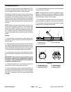
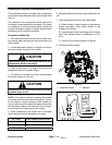
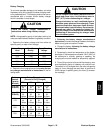
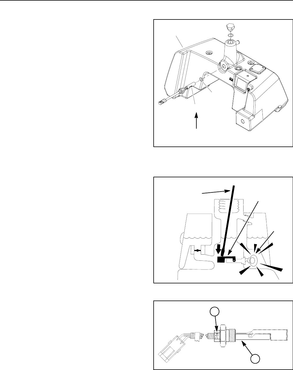
3. If oil level sensor was removed from reservoir, install
oil level sensor into reservoir making sure that arrow on
sensor is pointing down (Fig. 96). Torque sensor nut
from 110to140in-lb(12.5to15.8N-m).
4. Aftertesting, makesure that hydraulicoil level inres-
ervoir is correct.
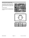
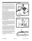
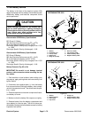
1. Hydraulic reservoir
2. Oil level sensor
3. O-ring
Figure 94
2
1
3
110 to 140 in- lb
(12.5to15.8N-m)
Figure 95
ALARM
(on)
FLOAT SWITCH
(lowered/closed)
CLEAN ROD OR
SCREWDRIVER
1. Oil level sensor 2. Sensor arrow
Figure 96
1
2